19
RUN
ERR
SF
II
I
0 1 2 3 7654
30 1 4 5 6 72
4 5 6 73210
BF
RUN STOP
CN4 EtherCATCN3 EtherNET
CN1 RS485
MFK
5
4
1
2
3
6
7
8
9
AM600-CPU1608TN
CN2 CAN
C N
5
3536
2 1
CANRUN
CANERR
Figure 9 RS485 communication terminal on CPU module
Channel Pin Function
COM0 (RS485)
1 RS485-
2 RS485+
5 GND0 COM0 power GND
COM1 (RS485)
6 RS485-
9 RS485+
3 GND1 COM1 power GND
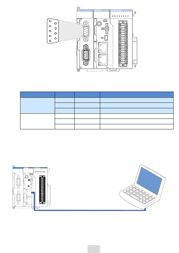
5.5 Ethernet Connection for Monitoring
Networking diagram
With the Ethernet port, the CPU module can be connected point-to-point with
devices such as a computer and HMI through an Ethernet cable:
.',
36/4501
$/34 $/ $"/
$/ &UIFS/&5 $/ &UIFS$"5
#'
4'
&33
36/
*
**
&UIFSOFUDBCMF
".$165/
$/
$"/36/
$"/&33
Figure 10 Connection between CPU module and PC
The CPU module can also be connected to a hub or switch, which is further
connected with other network devices, through an Ethernet cable to achieve
multi-point connection.
 Loading...


