8
Interface Name Function
USB Program download and commissioning
High-speed IO
16-point high-speed input
8-point high-speed output
I/O indicator
DIP switch RUN/STOP DIP switch
SD card interface Stores user programs and user data
MFK key Multi-functional key
Indicator
Operation indicator (RUN)
CPU module error indicator (ERR)
System error indicator (SF)
Bus error indicator (BF)
LED display Displays alarm information, and information for the MFK key
Local expansion bus
interface
Supports up to 16 local modules. The actual number
consumption. Hot plugging is not supported
24 V power input
terminal
DC 24 V voltage input, used with an AM600 power module
Grounding switch
For system digital GND and housing GND. Not used by
default. To ensure system stability, it should be only used
when the digital GND is used as a reference plane.
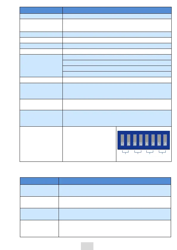
Termination resistor
DIP switch
ON means a resistor is
connected (the default is
OFF); 1 and 2 are for CAN, 3,
4, 7 and 8 are reserved, and 5
and 6 are for COM0 (RS485):
$"/
3FTFSWFE
34
3FTFSWFE
2.3 General Specications
Item
Programming
method
IEC 61131-3 programming languages (LD, FBD, IL, ST, SFC,
CFC)
Program execution
mode
Compile and run
User program
storage space
10 MB
Flash space for
power failure
memory
512 KB
 Loading...


