Chapter 2 Installation and Wiring
-
14
-
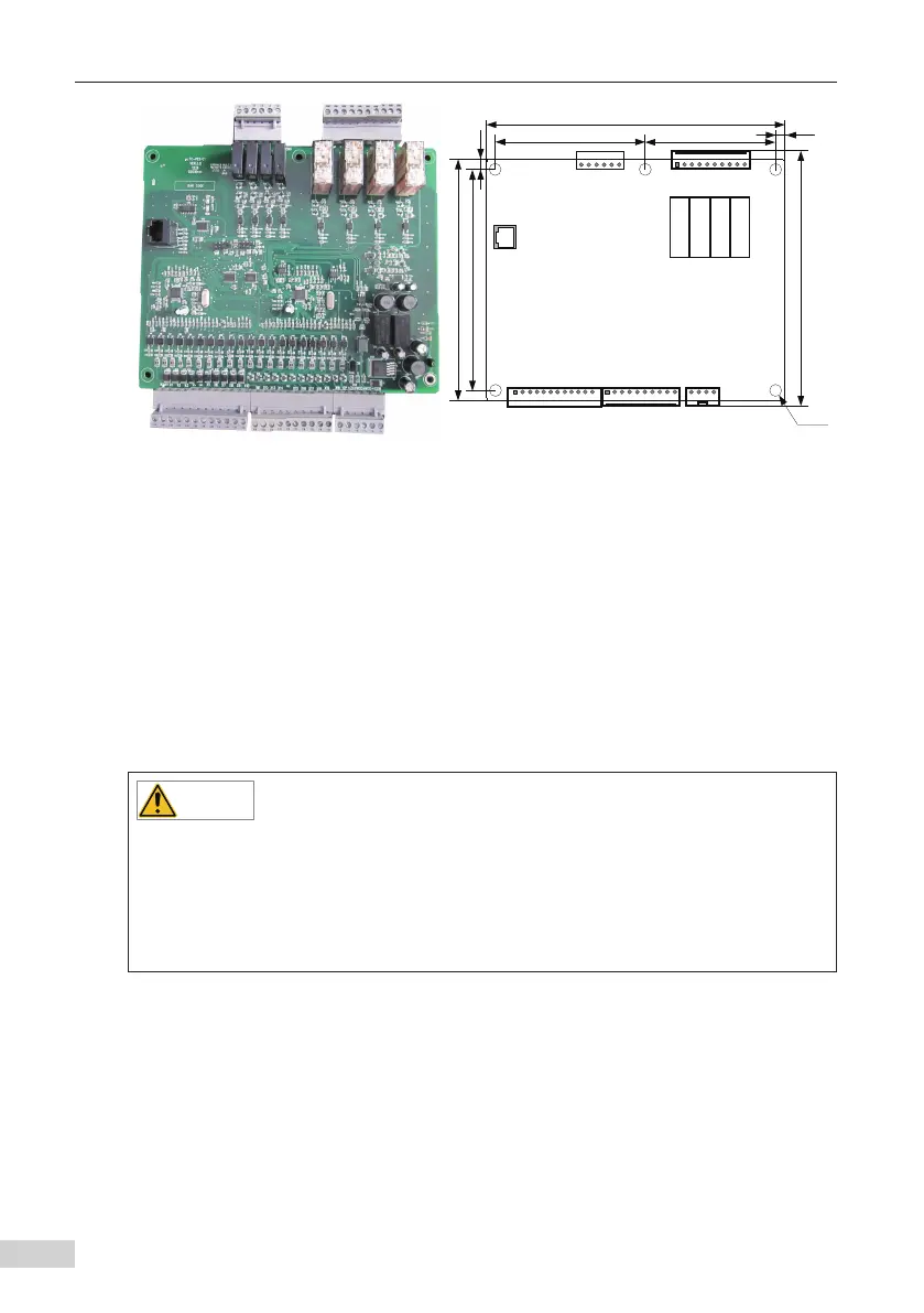
CN3 CN4 J3
CN1
101.0
148.0
162.0
7.0
88.0
201.0
178.0
6.0
Φ6.0
CN5
RJ45
Figure 2-2 Physical appearance of the control board
(Unit:mm)
2.1.3 Installation Instructions
To install the MCTC-PES-E1 system, do as follows:
1) Process the installation side in the main control cabinet. For the processing dimensions,
refer to Figure 2-1.
2) Mount the MCTC-PES-E1 on the installation side and fix it with screws.
If only the control board (without the protective guard) is required, do as follows:
1) Process the installation side in the main control cabinet. For the processing dimensions,
refer to Figure 2-2.
2) Mount the control board on the installation side and fix it with screws.
◆
The switching-mode power supply has been fixed on the protective guard of the MCTC-
PES-E1 system upon delivery.
◆
The screws for fixing the protective guard are not delivered together with the MCTC-
PES-E1 and you need to prepare them yourself. When selecting screws, consider the plate
thickness of the installation side, the thickness of the protective guard and the dimension of
the hole in Figure2-1.
2.2 Installation of Sensors
2.2.1 Technical Data of Sensors
The following table describes the technical data of the sensors.