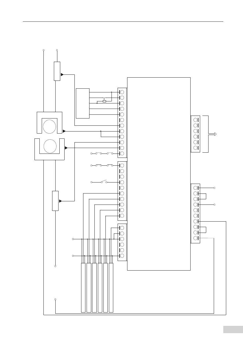
The following figure shows wiring of the MCTC-PES-E1 system.
Top MC
Switch 2
Bottom MC
Switch 2
Bottom MC
Switch 1
Switch 1
Reserved
Reserved
Reserved
Reserved
Reserved
Output of fault display (8421 code)
Manual reset switch
0V 0V 0V
Y3/M3/Y4/M4 connected to the control
circuit of the auxiliary brake
Power supply to service brake
Contactor
Power supply to
auxiliary brake
Contactor
Motor
Serivce brake
Auxiliary brake
Control system
for escalator
Y1/M1/Y2/M2 connected to the
safety circuit in series
Escalator speed phase A detection sensor
Escalator speed phase B detection sensor
Up step loss detection sensor
Down step loss detection sensor
Left handrail speed detection sensor
Right handrail speed detection sensor
Switching-mode
power supply
0V
24V
MCTC-PES-E1
M4
Y4
Y3/M3/Y4/M4
Controlling the
auxiliary brake
M2
Y2
M3
Y3
M1
COM
COM
431 2
Y1
MOD-
MOD+
DC-
DC+
OP
X20
Right handrail speed
detection
X18
Down step loss detection
X19
Left handrail speed detection
X17
Up step loss detection
X16
Escalator speed detection phase B
X15 Escalator speed detection phase A
X14
Manual reset signal
X11
Floor plate switch 2
X10
Floor plate switch 1
X9
Auxiliary brake detection
X5 Service brake signal
X6
Service brake detection1
X7
Service brake detection2
X8
Auxiliary brake signal
X4
System down signal
X3
System up signal
X2
NC inspection signal
X1
NO inspection sinal
E24V
Insp. down
lnsp. up
Insp.
24V-
24V+
Chain
wheel
Insp. = Inspection
MC = machine room
Top MC