Chapter 2 Installation and Wiring
-
18
-
2 DetectionPrinciple
Sensor 3/4 is used to measure the left/right handrail speed. The tachometer wheel is
driven by the handrail to rotate and its linear speed is basically consistent with the handrail
speed. An inductive part is set on the tachometer wheel to mount sensor 3/4 on a fixed
mechanical structure with the sensing face toward the inductive part.
When the tachometer wheel follows the handrail to rotate, sensor 3/4 outputs pulses, as
shown in Figure 3-5. A pulse is output every time the tachometer wheel rotates a revolution.
With the pulses and radius of the wheel, the system can measure the rotational speed of
the tachometer wheel. Then the system calculates the handrail speed and compares it
with the escalator/moving walkway speed. If the handrail speed is lower than 85% of the
corresponding escalator/moving walkway speed and the handrail underspeed continues
for 15s, the system cuts off the power supply to the safety circuit of the escalator/moving
walkway to stop the running, implementing protection.
2.2.4 Installing the Step/Pallet Loss Sensor
1 Installation
1) Installation position
For aluminum step or pallet, it is suggested to select NBN40-L2-E0-V1 (P+F), whose
detection distance is long and signal is reliable. Each step/pallet loss sensor is required for
the top and bottom machine rooms respectively. Install the sensor with the sensing face
toward the step beam to be detected.
2) Installation distance
5 mm ≤ L5 = L6 ≤ 15 mm
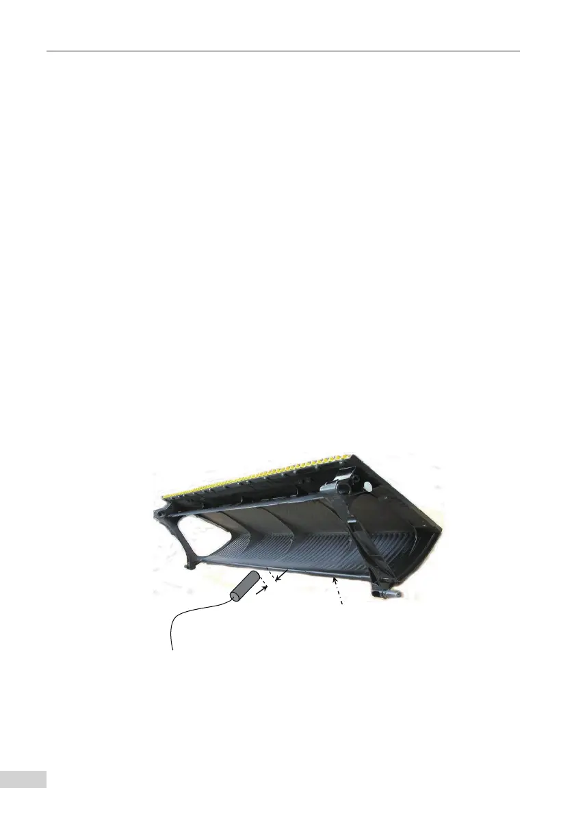
The following figure shows the installation position of sensor (5/6) for the escalator.
Step beam to be detected
L5/L6
Step/Pallet loss
sensor5/6
Step
Figure 2-5 Installation position of the step/pallet loss sensor