Chapter 2 Installation and Wiring
-
21
-
2.3 Wiring
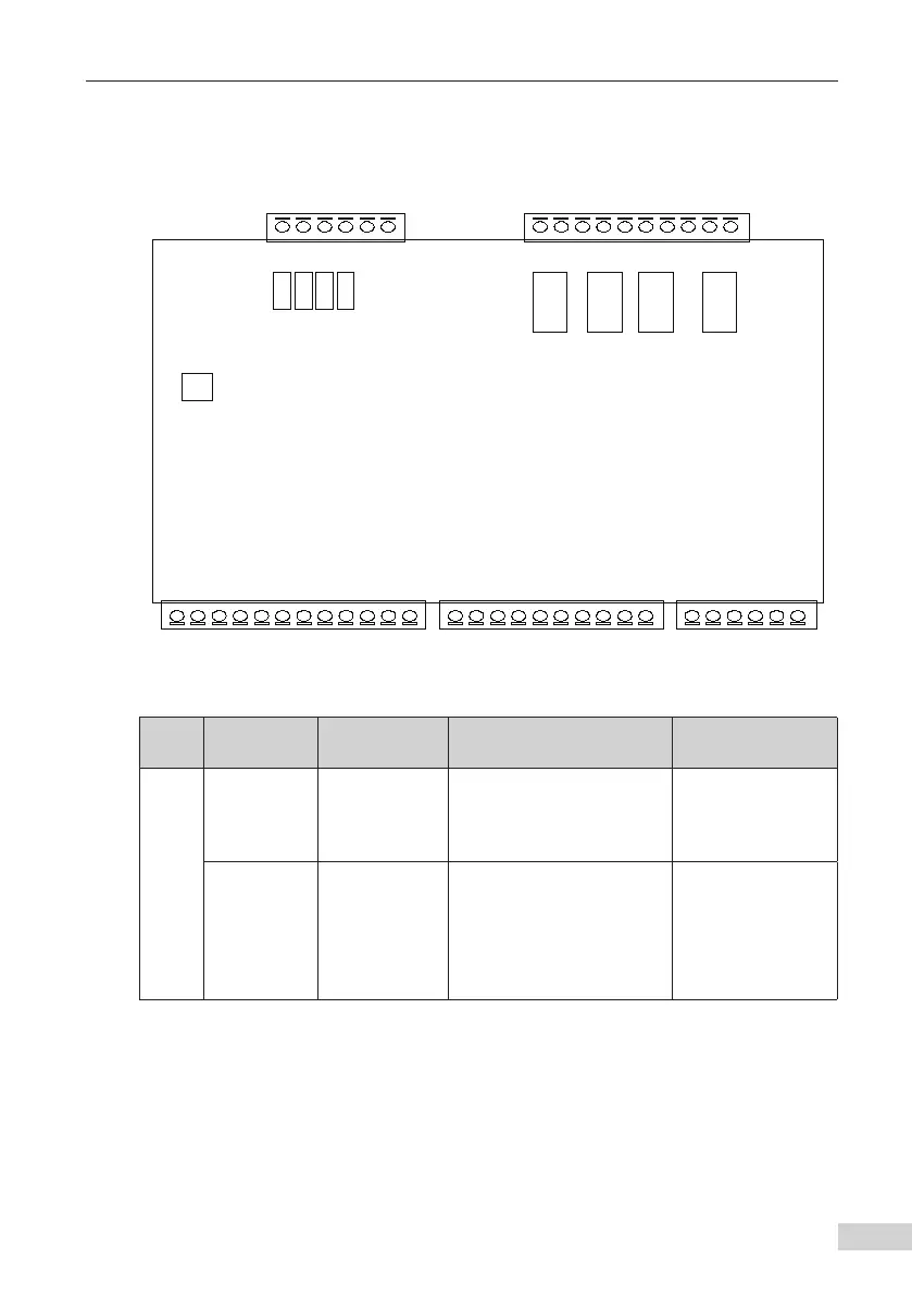
2.3.1 Description of System Terminals
The following figure shows the layout of the system terminals.
BIT4
BIT2
BIT1
BIT0
Reserved
MCTC-PES-E1
control board
M4
Y4
M2
Y2
M3
Y3
M1
BM
BM
Y1
MOD-
MOD+
DC-
DC+
OP
X20
X18
X19
X17
X16
X15
X14
X11
X10
X9
X5
X6
X7
X8
X4
X3
X2
X1
E24V
CN1
CN2
CN3
CN5
CN4
Reserved
J11
Reserved
Reserved
Reserved
Reserved
Figure 2-9 Layout of the system terminals
Table 2-3 Description of terminals of the MCTC-PES-E1
Type
Terminal
Symbol
Terminal
Name
Function Description Remark
Power/Communication
terminal (CN3)
DC+/DC-
24 V power
supply
The + 24 VDC power is
provided by specialized
switching-mode power
supply.
The switching-
mode power supply
complies with the
EN60950 standard.
MOD+/MOD-
Modbus
communication
It communicates with
Inovance NICE2000
integrated escalator
controller. When a safety
fault occurs, the NICE2000
displays the fault code.
The shielded twisted
cable is suggested.