Chapter 4 Functional Parameters
-
35
-
It indicates the detected braking-to-stop distance after stop.
Parameter Name Setting Range Factory Setting Unit Operation
F1-06
Pulse time interval of
left handrail
- 0 s
●
F1-07
Pulse time interval of
right handrail
- 0 s
●
They indicate the actually detected cycles of left and right handrail signals (no display
during inspection).
Parameter Name Setting Range Factory Setting Unit Operation
F1-08
Number of phase A
pulses between two
up step signals
- 0 -
●
F1-09
Number of phase B
pulses between two
up step signals
- 0 -
●
F1-10
Number of phase A
pulses between two
down step signals
- 0 -
●
F1-11
Number of phase
B pulses between
down step signals
- 0 -
●
They indicate the actually detected number of phase A/B pulses between two step signals
(no display during inspection).
Parameter Name Setting Range Factory Setting Unit Operation
F1-12
States of I/O
terminals
- 0 -
●
F1-13
States of I/O terminal
functions
- 0 -
●
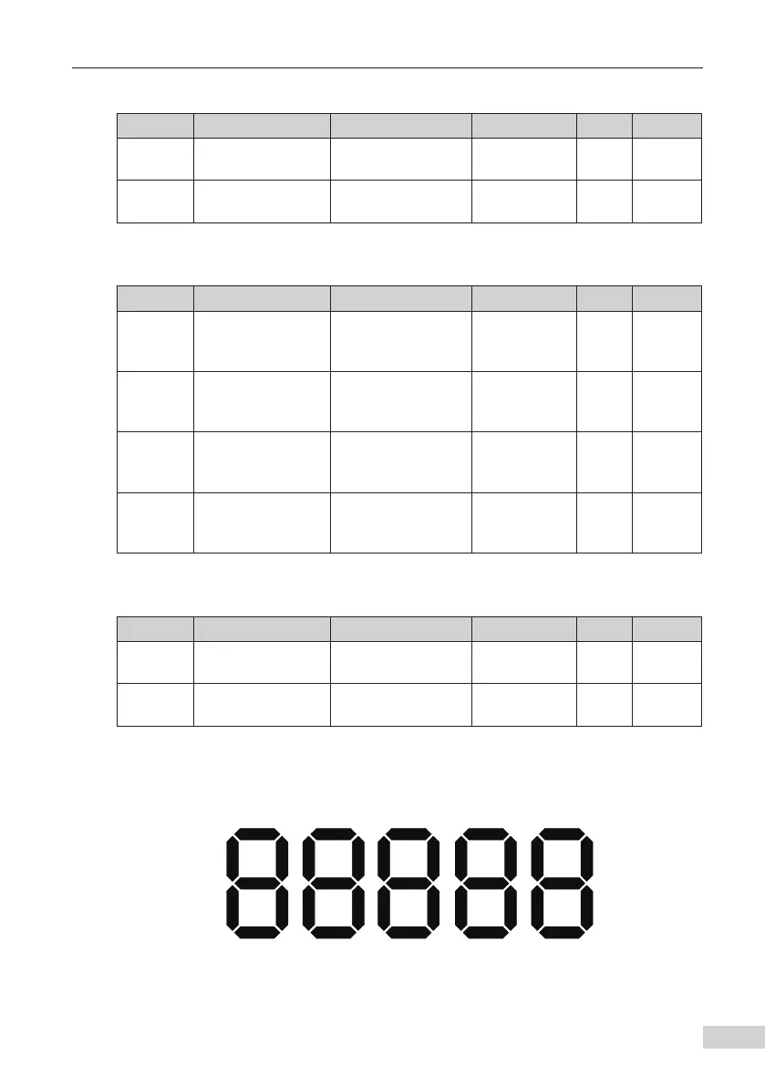
F1-12 indicates the states of the I/O terminals. F1-13 indicates the states of the I/O
terminal functions.
The states are displayed by the following 5-digit LEDs.
X5
X14
X15
X20
LED 5
X4
X12
X13
X19
Y4
Y4F
LED 4
X3
X10
X11
X18
Y3
Y3F
LED 3
X2
X8
X9
X17
Y2
Y2F
LED 1
Y1F
Y1
X16
X7
X6
X1
LED 2
Figure 4-1 LED indicating the states of the I/O terminals and their functions