Electrical Design Guide
‑34‑
3.2.2.2 Power Cable Types
For details, see "
3.2.1.2 Power Cable Types
"
on page 26
.
3.2.2.3 Power Cable Specifications
For details, see "
3.2.1.3 Power Cable Specifications
"
on page 28
.
3.2.2.4 Power Cable Shield
Take proper shielding measures in the following locations to prevent equipment
damage:
● Locations with interference caused by static electricity
● Locations with strong electric field or magnetic field
● Locations with radioactive rays
It is recommended to use the shielded cable as the motor output cable. Perform a
360° connection on the shield structure by using the shield grounding bracket, and
crimp the drain wire of the shield to the PE terminal. Connect the shielded cable with
shielded iron plate at the grounding end of the equipment for 360°, and avoid
connecting the shielding layer to the casing in the form of "pig tail", otherwise, it will
become high impedance for high frequency noise. If the shielding must be
disconnected to install the motor contactor, the shielding must be kept continuous
and its high frequency impedance as low as possible.
See "
Figure 3–7 Connection of the shielding layer
"
on page 34
for the correct
connection of the shielding layer. Connect the shielding wire to the drive for 360° and
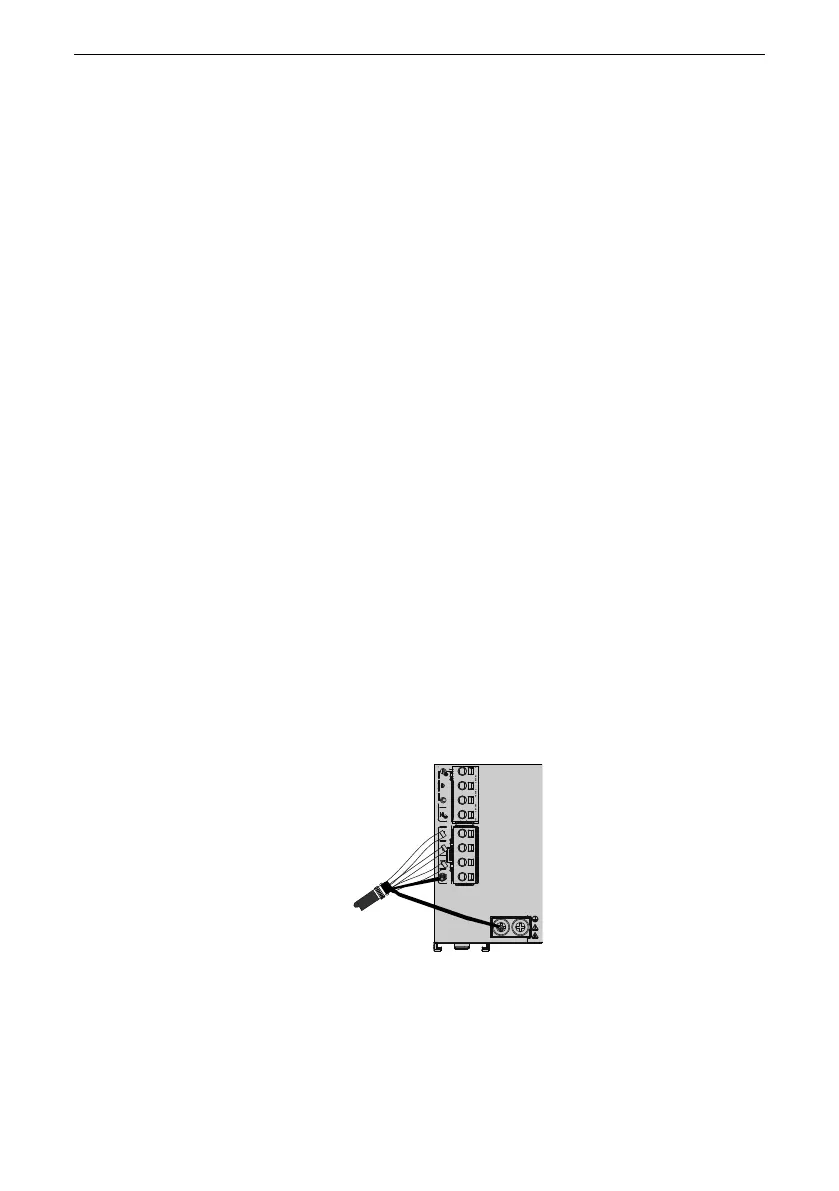
avoid pig tail connection as possible. In the figure, the red line is the power line
shielding layer, and the yellow line and blue line are the IO signal line shielding layer.
Figure 3‑7 Connection of the shielding layer
Grounding bracket of the power cable shield.
Keep the lead wire of the motor cable shield as short as possible, with its width (b in
the following figure) not shorter than 1/5 of its length (a in the following figure).

 Loading...


