Terminals
‑92‑
Table 4–24 Recommended cable between the servo drive and linear motor encoder
Cable Size
Ω/km
Allowable Length (m)
26 AWG (0.13 mm
2
)
143 8.0
25 AWG (0.15 mm
2
)
89.4 14.0
24 AWG (0.21 mm
2
)
79.6 15.0
23 AWG (0.26 mm
2
)
68.5 18.0
22 AWG (0.32 mm
2
)
54.3 23.0
21 AWG (0.41 mm
2
)
42.7 29.0
Suppose the current consumed by the motor encoder is higher than 200 mA,
you can select the cable based on the following formula.
Where, △U is 0.5 V, I
encoder
represents the current consumed by the encoder (see the
encoder user guide for details), and R
unit
represents the unit resistance (Ω/km) of the
cable.
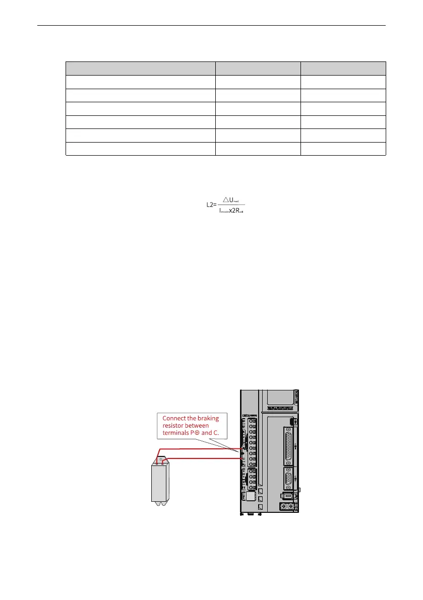
4.8 Wiring of the External Regenerative Resistor
Connecting the regenerative resistor
When the motor torque direction is opposite to the direction of rotation, the energy is
fed back to the servo drive from the motor side, leading to bus voltage rise. Once the
bus voltage rises to the braking threshold, the excessive energy must be consumed by
a regenerative resistor. Otherwise, the servo drive will be damaged. The regenerative
resistor can be a built‑in or an external one. However, a built‑in regenerative resistor
cannot be used together with an external one.
Figure 4‑24 Wiring of external regenerative resistor

 Loading...


