Terminals
‑60‑
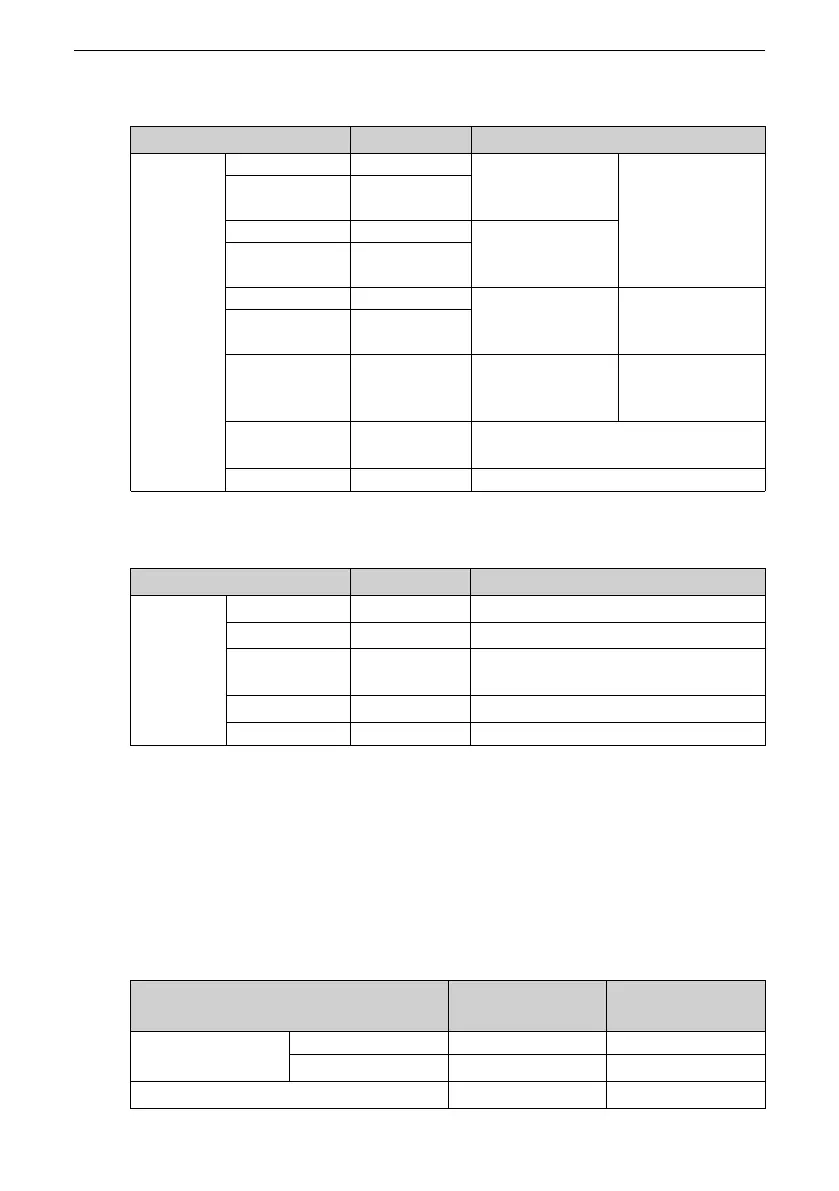
Table 4–9 Specifications of encoder frequency‑division output signals
Signal Name
Pin No. Function
General
PAO+ 21
Phase A frequency‑
division output
signal
Quadrature
frequency‑division
pulse output
signals of phases A
and B
PAO– 22
PBO+ 25
Phase B frequency‑
division output
signal
PBO– 23
PZO+ 13
Phase Z frequency‑
division output
signal
Home pulse output
signal
PZO– 24
PZ‑OUT 44
Phase Z frequency‑
division output
signal
Home pulse open‑
collector output
signal
GND 29
Home pulse open‑collector output
signal ground
PE
Enclosure
‑
Table 4–10 Specifications of AI/AO signals
Signal Name
Pin No. Function
General
AO1 15
Analog output
GND 19
Common terminal of AI/AO
AI1 20
Voltage‑type AI 1
Voltage range: –10 V to +10 V
GND 16
Power ground
PE
Enclosure
‑
4.2.2 Position Reference Input Signals
For descriptions of position reference input signals, see "
Table 4–7
"
on page 58
.
The reference pulses and signs on the host controller side can be outputted through
the differential drive or open‑collector. The following table lists the maximum input
frequency and minimum pulse width.
Table 4–11 Relation between pulse input frequency and pulse width
Pulse Mode
Maximum Frequency
(pps)
Minimum Pulse
Width (us)
Low‑speed
Differential 500 k
1
Open‑collector
200 k
2.5
High‑speed differential
4 M 0.125

 Loading...


