37
System components
Product Support: www.instron.com
6. Re-insert the card into the connector with the indicator pinpointing away from the
connector. Ensure that the card is fully seated.
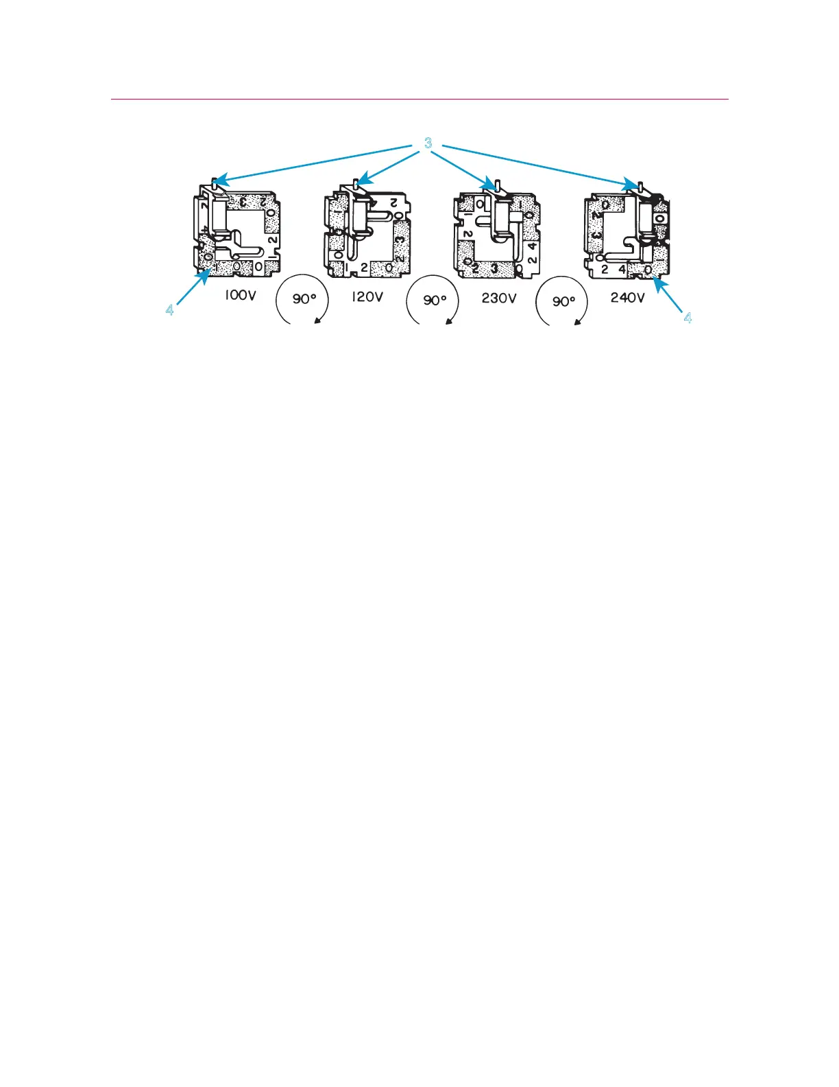
7. If necessary, change the fuse holder. Refer to “Replace a Fuse” on page 118 for
instructions on replacing a fuse.
8. Re-install the fuse holder into the connector. Ensure that the indicator pin now indi-
cates the correct input voltage. See Figure 4 on page 34 for reference.
9. Reconnect the power cable to mains power and turn on the system. Verify that the
white
DISABLED indicator on the indicator panel illuminates.
10. Before you carry out any testing, perform the procedure described in “First time
startup” on page 47.
System components
Instron
®
Service installs your testing system. These diagrams and instructions are
provided as a reference if you need to move the system after the initial installation.

 Loading...


