41
Accessory Mounting Dimensions
Product Support: www.instron.com
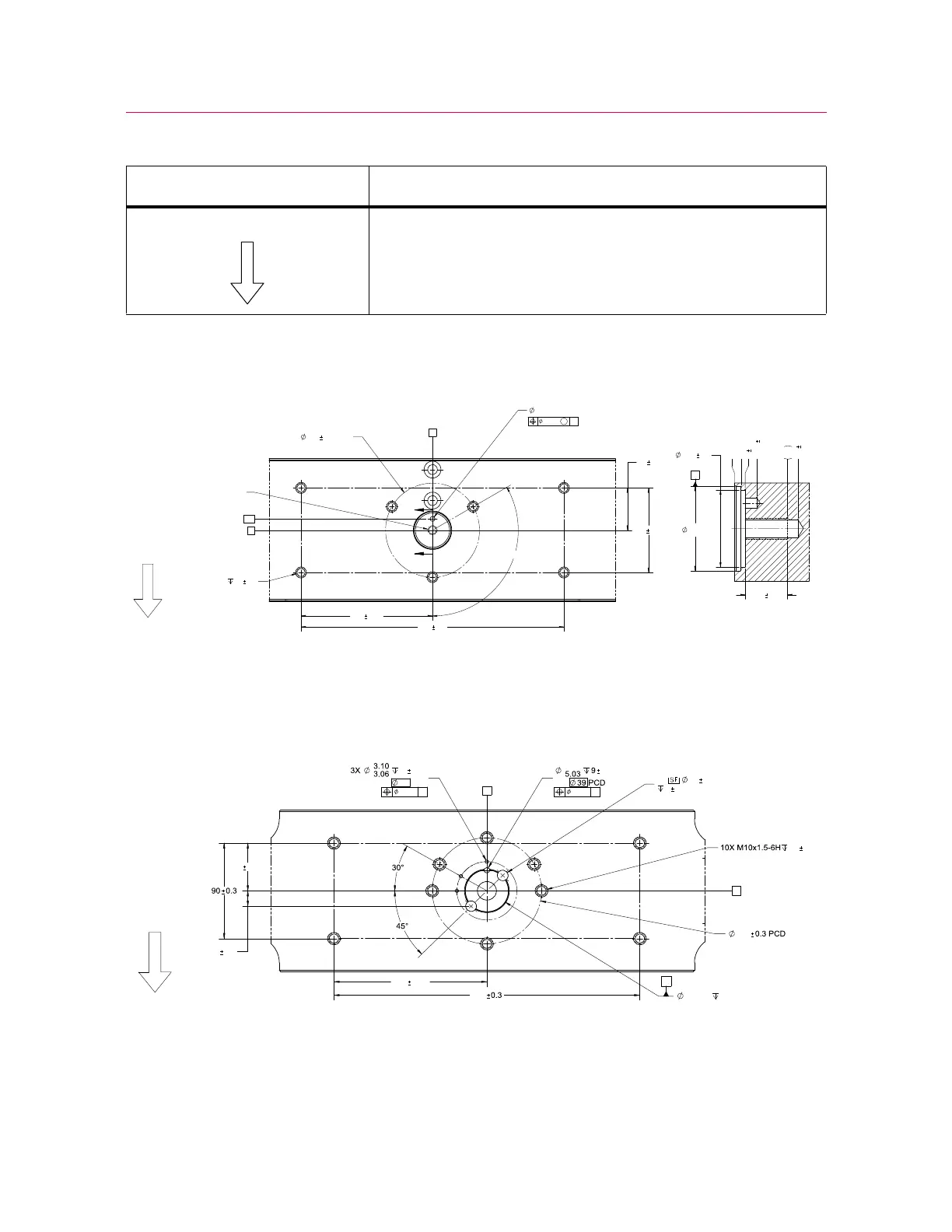
Base beam dimensions
Figure 6. View of base beam from above
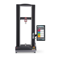
Crosshead dimensions
Figure 7. View of underside of crosshead
arrow pointing to the front of the load frame
Table 11. Meaning of symbols on dimension drawings (Continued)
Symbol on drawing Meaning
0[+
;0[+
7<3
3&'
(
(
0
$
0,1
6(&7,21((
$
5.08
0.15
ON
5 0.15
ON
55 PCD
45
0.15
14.5
0.5
140
0.15
280
40.038
40.000
3.00 MIN
2X
10 0.5
6 0.5
25 0.5
100
0
0
0.05
A
0.05
A
A