17
System Description and Terminology
Product Support: www.instron.com
Components
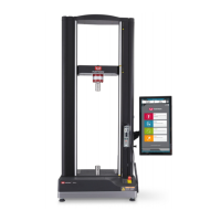
The major components of an Instron
®
electromechanical testing system include:
• Load frame with integral controller
• Load cell mounted to the crosshead
• Grips for tension testing or table-mounted anvils on a platen for compression
testing.
• Instron
®
approved computer system with Instron Bluehill
®
software.
Special fixtures are available for applications such as flexure and peel testing. For strain
measurement, an optional strain gauge extensometer attaches to the specimen. You
can use non-contacting extensometers with specimens that are unable to support a
contacting extensometer. Contact your regional Instron
®
office or check our web site at
www.instron.com for assistance with Instron’s grips and fixtures.
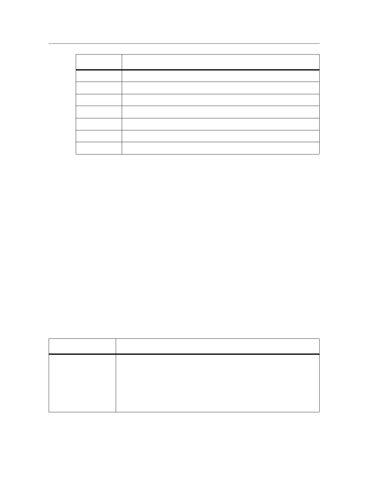
The following table defines the components of the testing system:
3Rear panel
4 Controller panel
5Frame base
6 Base beam
7 Base adapter
8Crosshead
9Ballscrew cover
Label Component
Table 1. Testing System Components
Component Description
Load Frame The load frame comprises a base, one or two columns, a moving crosshead,
and a top plate. It is a high stiffness support structure against which the test
forces react.
Each column comprises a guide column and a ballscrew. The crosshead is
mounted on both the guide column and the ballscrew. Rotation of the
ballscrew drives the crosshead up or down while the guide column provides
stability.