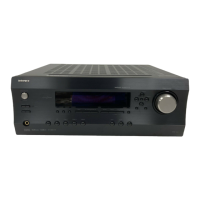
DTR-4.6
IC BLOCK DIAGRAMS AND DESCRIPTIONS
CS42528 (8-Ch Codec with S/PDIF Receiver)
TERMINAL DESCRIPTION
Pin Name #
Pin Description
CX_SDIN1
CX_SDIN2
CX_SDIN3
CX_SDIN4
1
64
63
62
Codec Serial Audio Data Input (Input) - Input for two's complement serial audio data.
CX_SCLK CODEC Serial Clock (Input/Output) - Serial clock for the CODEC serial audio interface
CX_LRCK
VD
DGND
VLC
SCL/CCLK
SDA/CDOUT
AD1/CDIN
CODEC Left Right Clock (Input/ Output) - Determines which channel, Left or Right, is currently active on
the CODEC serial audio data line.
Digital Power (Input) - Positive power supply for the digital section.
Digital Ground (Input) - Ground reference. Connects to digital ground.
Control Port Power (Input) - Determines the required signal level for the control port.
Serial Control Port Clock (Input) - Serial clock for the serial control port.
Serial Control Data (Input/Output) - SDA is a data I/O line in IC mode and requires an external pull-up
resistor to the logic interface voltage. CDOUT is the output
data line for the control port interface in SPI mode.
Address Bit 1 (I C)/Serial Control Data (SPI) (Input) - AD1 a chip address pin in I C mode; CDIN is
the input data line for control port interface in SPI mode.
2
3
4
51
5
52
6
7
8
9
2
2
AD0/CS 10 Address Bit 0 (I C)/Control Port Chip Select (SPI) (Input) - AD0 is a chip address pin in I C mode; CS
is the chip select signal in SPI mode.
INT 11 Interrupt (Output) - The CS42518 will generate an interrupt condition as per the Interrupt Mask register.
RST 12 Reset (Input) - The device enters a low power mode and all internal registers are reset to their default
settings when low.
AINR-
AINR+
13
14
Differential right Channel Analog Input (Input) - Signals are presented differentially to the delta-sigma
modulators via the AINR+/- pins.
AINL-
AINL+
15
16
Differential right Channel Analog Input (Input) - Signals are presented differentially to the delta-sigma
modulators via the AINR+/- pins.
VQ 17 Quiescent Voltage (Output) - Filter connection for internal quiescent reference voltage.
FILT+ 18 Positive Voltage Reference (Output) - Positive reference voltage for the internal sampling circuits.
REFGND 19 Reference Ground (Input) - Ground reference for the internal sampling circuits.
AOUTA1 +, -
AOUTB1 +, -
AOUTA2 +, -
AOUTB2 +, -
AOUTA3 +, -
AOUTB3 +, -
AOUTA4 +, -
AOUTB4 +, -
36, 37
35, 34
32, 33
31, 30
28, 29
27, 26
22, 23
21, 20
Differential Analog Output (Output) - The full-scale differential analog output level is specified in the
Analog Characteristics specification table.
2
2
VA
VARX
24
41
Analog Power (Input) - Positive power supply for the analog section.
AGND
25
40
Analog Ground (Input) - Ground reference. Connectes to analog ground.
w
w
w
.
x
i
a
o
y
u
1
6
3
.
c
o
m
Q
Q
3
7
6
3
1
5
1
5
0
9
9
2
8
9
4
2
9
8
T
E
L
1
3
9
4
2
2
9
6
5
1
3
9
9
2
8
9
4
2
9
8
0
5
1
5
1
3
6
7
3
Q
Q
TEL 13942296513 QQ 376315150 892498299
TEL 13942296513 QQ 376315150 892498299
http://www.xiaoyu163.com
http://www.xiaoyu163.com

 Loading...