95
Setup Menu
Speaker/Output Setup
—Continued
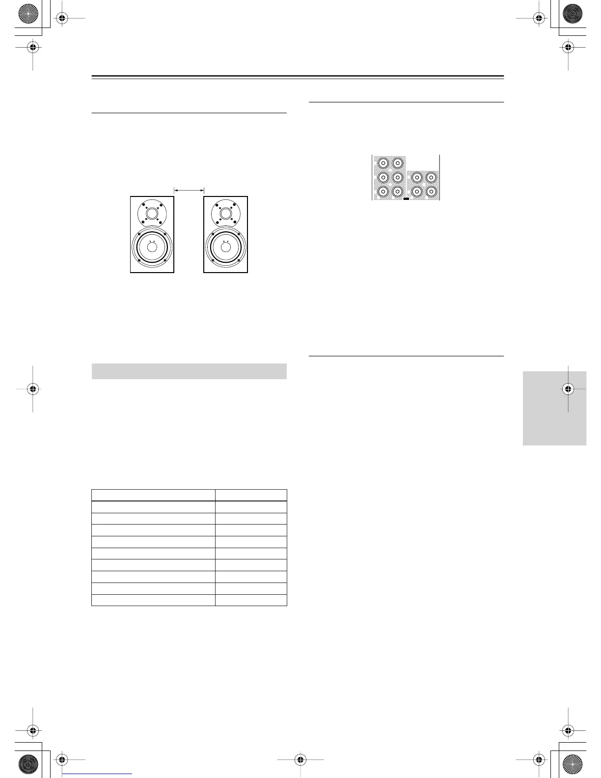
Distance Between Surr Back A SP/
Distance Between Surr Back B SP
This setting is allowed only when “Main 2ch” is
selected from the Speaker Configuration sub-menu.
Place two surround back speakers as close together as
possible, measure the distance, and set the value (see
the figure). The maximum effects will be realized by
THX’s ASA* technology.
0-1 ft (0-0.3 m)(Default):
This is the setting when the
distance between the speakers is 0-1 foot (0-30 cm).
1-4 ft (0.3-1.2 m):
This is the setting when the distance
between speakers is 1-4 feet (30 cm-1.2 m).
>4 ft (1.2 m):
This is the setting when the distance
between speakers is 4 feet (1.2 m) or more.
*
ASA:
Advanced Speaker Array
This setting allocates audio output jacks on the
RDC-7.1 to input (play) sources. The setting varies
depending on the connection conditions.
The RDC-7.1 is equipped with analog output jacks for
five lines, and digital output jacks: optical jacks (OPT)
for two lines, and coaxial jacks (COAX) for two lines. If
setting the analog jacks to “Zone 2 Out” or “Zone 3
Out,” you can also specify whether output should be
variable or fixed.
The default settings are as follows:
Analog 1-5
Set the analog audio output jacks of “AUDIO OUT 1-5.”
You can select from Tape 1 Rec Out, Tape 2 Rec Out,
Video 1 Rec Out, Video 2 Rec Out, Video 3 Rec Out,
Zone 2 Out, Zone 3 Out, and Not Used.
Example 1:
When input (REC) of an audio recording device (e.g., a
cassette deck) with TAPE 1 as an input source is
connected to AUDIO OUT 1, set “Analog 1” to “Tape 1
Rec Out.”
Example 2:
When sound input of a picture recording device (e.g., a
VCR) with VIDEO 1 as an input source is connected to
AUDIO OUT 2, set “Analog 2” to “Video 1 Rec Out.”
Example 3:
When the amplifier for Zone 2 is connected to AUDIO
OUT 5, set “Analog 5” to “Zone 2 Out.”
When nothing is connected:
Select “Not Used.”
Zone 2 Out, Zone 3 Out
This item is displayed when “Zone 2 Out” or “Zone 3
Out” is specified for Analog 1-5 above. The default
setting for “Zone 2 Out” is “Pre Out (variable)” and for
“Zone 3 Out” is “Line Out (fixed).”
Pre Out (variable):
Select this when you want to set
“variable” for output to a device connected to Zone 2 or
Zone 3. You should operate the RDC-7.1 to adjust the
sound volume from the device in Zone 2 or Zone 3.
Line Out (fixed):
Select this when you want to set
“fixed” for output to a device connected to Zone 2 or
Zone 3. You should operate the amplifier connected to
the terminal to adjust the sound volume from the device
in Zone 2 or Zone 3.
Audio Output Assign Sub-menu
Terminals Default input settings
Analog 1 (AUDIO OUT 1) Video 1 Rec Out
Analog 2 (AUDIO OUT 2) Video 2 Rec Out
Analog 3 (AUDIO OUT 3) Video 3 Rec Out
Analog 4 (AUDIO OUT 4) Zone 2 Out
Analog 5 (AUDIO OUT 5) Zone 3 Out
Opt 1 Out (DIGITAL OUT OPTICAL 1) Tape 1 Rec Out
Opt 2 Out (DIGITAL OUT OPTICAL 2) Tape 2 Rec Out
Coax 1 Out (DIGITAL OUT COAXIAL 1) Video 1 Rec Out
Coax 2 Out (DIGITAL OUT COAXIAL 2) Zone 2 Out
1
2
3
4
5
OUT
LR R L
AUDIO