136 21555 Non-Transparent PCI-to-PCI Bridge User Manual
List of Registers
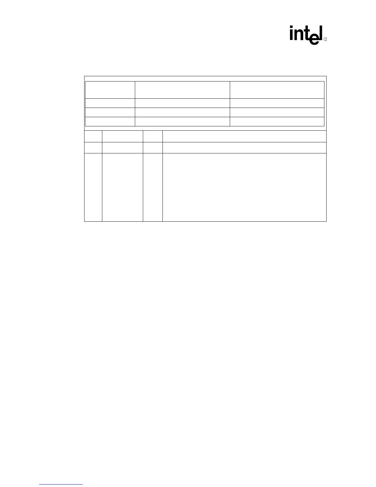
Table 41. Downstream I/O or Memory 1 and Upstream I/O or Memory 0 Translated Base Register
Bit Name R/W Description
5:0 Reserved R Reserved. Returns 0 when read.
31:6 XLAT_BASE R/W
Contains the translated base address for downstream or upstream
transactions whose initiator bus addresses fall into either the
Downstream I/O or Memory 1, or Upstream I/O or Memory 0 Base
Address range.
The number of bits that are used for the translated base is determined by
the setup register corresponding to that base address and also matches
the number of writable bits in the corresponding BAR.
The remaining bits may be written but are ignored when performing
address translation. When an I/O or memory transaction is initiated by the
21555 on the target bus, the original base address is replaced with the
value contained in this register.
Offsets
Downstream I/O or Memory 1
Translated Base
Upstream I/O or Memory 0 Translated
Base
Primary byte 9B:98h A7:A4h
Secondary byte 9B:98h A7:A4h
CSR byte 06F:06Ch 07B:078h