172 21555 Non-Transparent PCI-to-PCI Bridge User Manual
List of Registers
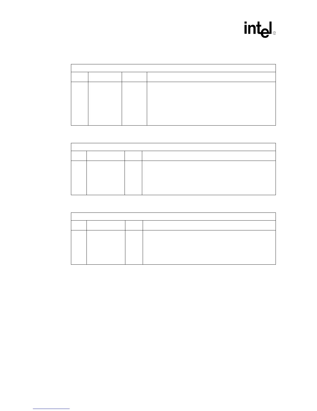
Table 99. Upstream Page Boundary IRQ 1 Register
Byte Offset: 08F:08Ch
Bit Name R/W Description
31:0 PAGE1_IRQ R/W1TC
Each bit in this register corresponds to a page entry in the upper half
of the Upstream Memory 2 range. Bit 0 corresponds to the 33
rd
page, and bit 31 corresponds to the 64
th
(highest order) page. The
21555 sets the appropriate bit when it successfully transfers data to/
from the initiator that addresses the last Dword in a page.
When the Upstream Page Boundary 1 IRQ Mask bit corresponding
to that page is zero, the 21555 asserts s_inta_l.
Reset value is 0
Table 100. Upstream Page Boundary IRQ Mask 0 Register
Byte Offset: 093:090h
Bit Name R/W Description
31:0 PAGE0_MASK R/W
• When 0, the 21555 asserts s_inta_l when the corresponding
status bit in the Upstream Page Boundary IRQ 0 register is set.
• When 1, the 21555 does not assert s_inta_l when the
corresponding status bit in the Upstream Page Boundary IRQ 0
register is set.
• Reset value is FFFFFFFFh
Table 101. Upstream Page Boundary IRQ Mask 1 Register
Byte Offset: 097:094h
Bit Name R/W Description
31:0 PAGE1_MASK R/W
• When 0, the 21555 asserts s_inta_l when the corresponding
status bit in the Upstream Page Boundary IRQ 1 register is set.
• When 1, the 21555 does not assert s_inta_l when the
corresponding status bit in the Upstream Page Boundary IRQ 1
register is set.
• Reset value is FFFFFFFFh