21555 Non-Transparent PCI-to-PCI Bridge User Manual 171
List of Registers
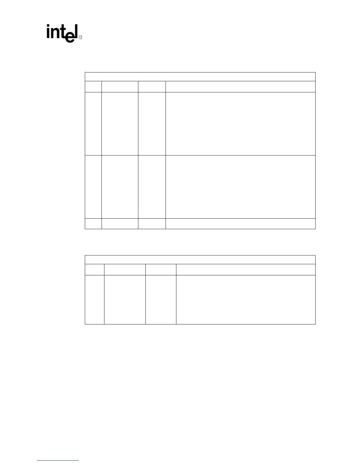
Table 97. Chip Clear IRQ Mask Register
Byte Offsets: 087:086h
Bit Name R/W Description
0 Clr_D0M R/W1TC
• When 0, signal s_inta_l is asserted on the 21555’s secondary
interface when the corresponding chip event bit is a 1, indicating a
return of power state to D0.
• When 1, the corresponding chip event bit does not generate an
interrupt.
Writing a 1 to a bit in this register clears the Chip IRQ Mask bit to
0.
Writing a 0 to any bit in this register has no effect. Reading this
register returns the current status of the Chip IRQ Mask bits.
• Reset value is 1
1 Clr_Sstat R/W1TC
• When 0, p_inta_l is asserted on the 21555’s primary interface
when the corresponding chip event bit, indicating a deasserting
edge on s_pme_l, is a 1.
• When 1, the corresponding chip event bit does not generate an
interrupt.
Writing a 1 to a bit in this register clears the Chip IRQ Mask bit to
0.
Writing a 0 to any bit in this register has no effect. Reading this
register returns the current status of the Chip IRQ Mask bits.
• Reset value is 1
15:2 Reserved R Reserved. Returns 0 when read.
Table 98. Upstream Page Boundary IRQ 0 Register
Byte Offset: 08B:088h
Bit Name R/W Description
31:0 PAGE0_IRQ R/W1TC
Each bit in this register corresponds to a page entry in the lower
half of the Upstream Memory 2 range. Bit 0 corresponds to the
first (lowest order) page, and bit 31 corresponds to the 32
nd
page.
The 21555 sets the appropriate bit when it successfully transfers
data to/from the initiator that addresses the last Dword in a page.
When the Upstream Page Boundary 0 IRQ Mask bit
corresponding to that page is zero, the 21555 asserts s_inta_l.
Reset value is 0