Intel® 460GX Chipset Software Developer’s Manual 11-25
LPC/FWH Interface Configuration
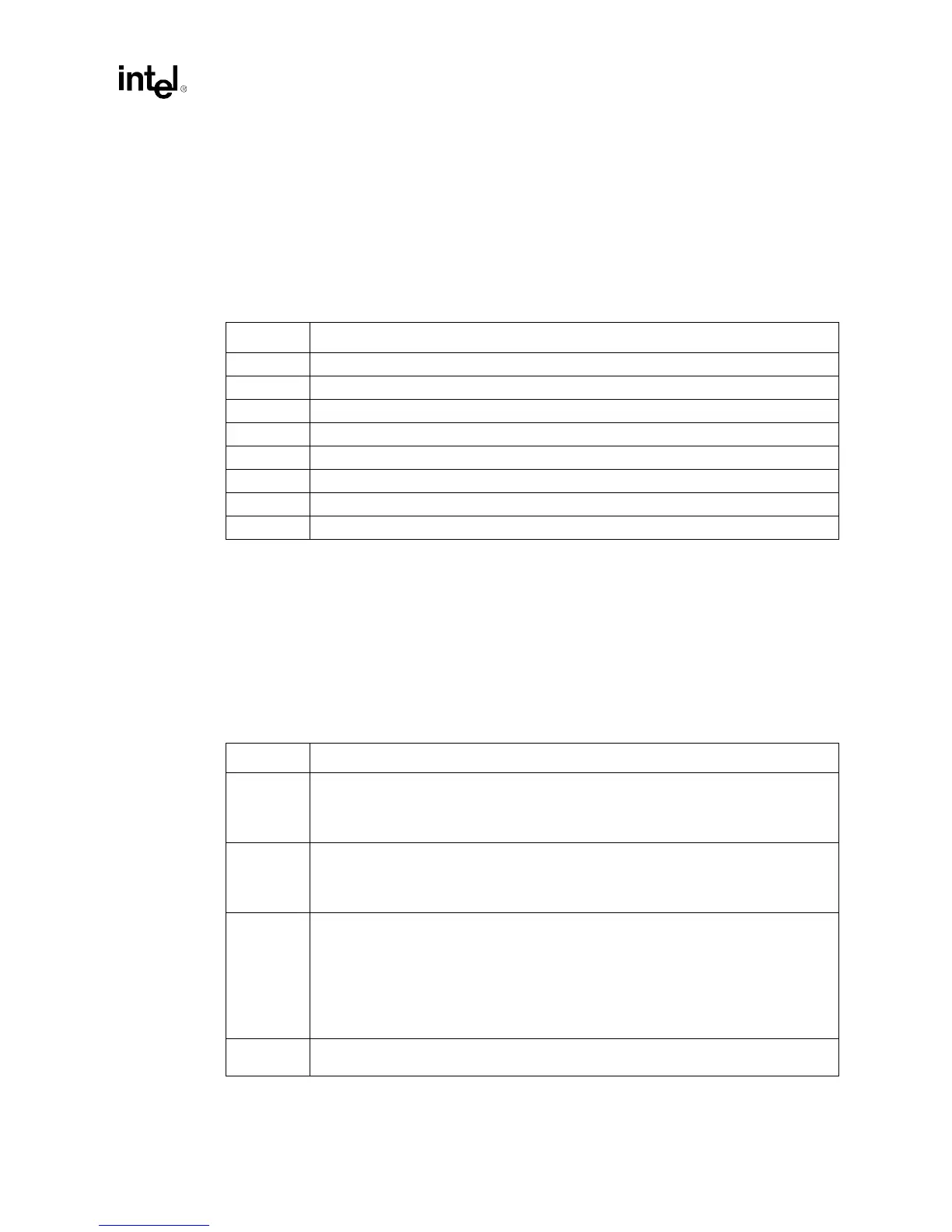
11.2.2.10 Elcr2–Edge/Level Control Register (I/O)
I/O Address: INT CNTRL-2–4D1h
Default Value: 00h
Attribute: Read/Write
ELCR2 register allows IRQ[15,14,12:9] to be edge or level programmable on an interrupt by
interrupt basis. Note that, IRQ[13,8#] are not programmable and are always edge sensitive. When
level triggered, the interrupt is signaled active when input IRQ signal is high.
11.2.3 Counter/Timer Registers
11.2.3.1 Tcw–Timer Control Word Register (I/O)
I/O Address: 043h
Default Value: All bits undefined
Attribute: Write Only
Bit Description
7 IRQ15 ECL. 0 = Edge Triggered mode; 1 = Level Triggered mode.
6 IRQ14 ECL. 0 = Edge Triggered mode; 1 = Level Triggered mode.
5 Reserved. Must be 0.
4 IRQ12 ECL. 0 = Edge Triggered mode; 1 = Level Triggered mode.
3 IRQ11 ECL. 0 = Edge Triggered mode; 1 = Level Triggered mode.
2 IRQ10 ECL. 0 = Edge Triggered mode; 1 = Level Triggered mode.
1 IRQ9 ECL. 0 = Edge Triggered mode; 1 = Level Triggered mode.
0 Reserved. Must be 0.
Bit Decription
7:6 Counter Select. The Read Back Command is selected when bits[7:6] are both 1.
Bit[7:6] Function Bit[7:6] Function
00 Counter 0 select 10 Counter 2 select
01 Counter 1 select 11 Read Back Command
5:4 Read/Write Select. The Counter Latch Command is selected when bits[5:4] are both 0.
Bit[5:4] Function Bit[5:4] Function
00 Counter Latch Command 10 R/W Most Significant Byte
01 R/W Least Significant Byte 11 R/W LSB then MSB
3:1 Counter Mode Selection. Bits [3:1] select one of six possible counter modes.
Bit[3:1] Mode Function
000 0 Out signal on end of count (=0)
001 1 Hardware re-triggerable one-shot
X10 2 Rate generator (divide by n counter)
X11 3 Square wave output
100 4 Software triggered strobe
101 5 Hardware triggered strobe
0 Binary/BCD Countdown Select. 0=Binary countdown. The largest possible binary count is
2
16
. 1=Binary coded decimal (BCD) count is used. The largest BCD count allowed is 10
4
.