Intel® 460GX Chipset Software Developer’s Manual 15-9
PCI/LPC Bridge Description
During the Sample phase, the device drives SERIRQ low if the corresponding interrupt signal is
low. If the corresponding interrupt is high, then the devices will tri-state the SERIRQ signal. It will
remain high due to pull-up resistors.
During the other two phases (turnaround and recovery), no device should drive the SERIRQ signal.
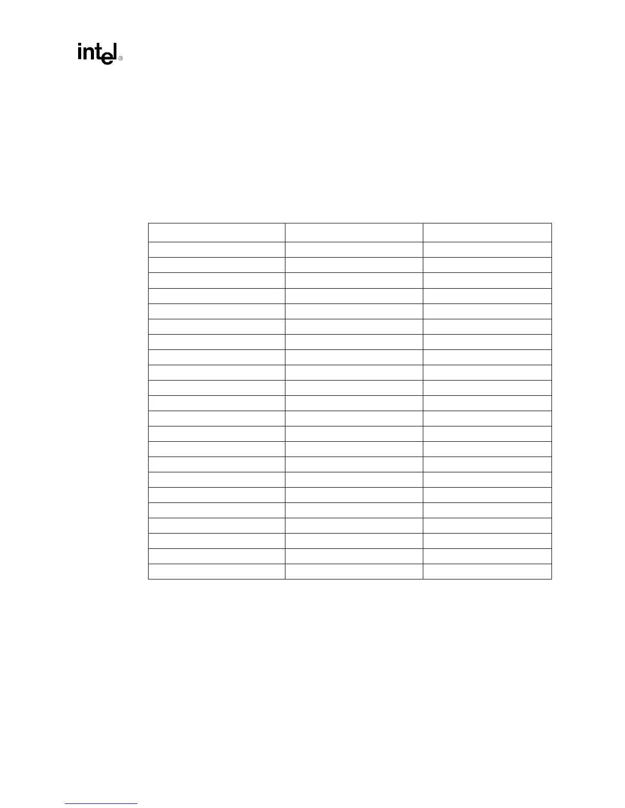
The IRQ/DATA frames have a specific order and usage, as shown in Table 15-1.
If an SMI# is activated on frame 3, the IFB will drive its SMI# signal low. This will then generate
an SMI# to the microprocessor if enabled.
15.3.1.4 Stop Frame
After all of the data frames, a Stop Frame will be done by the IFB. The IFB will drive SERIRQ low
for 2-3 PCI clocks. The number of clocks determines the next mode:
• If SERIRQ is low for 2 clocks, then the next mode is the Quite Mode. Any device may initiate
a Start Frame in the second clock (or more) after the rising edge of the Stop Frame.
• If SERIRQ is low for 3 clocks, then the next mode is the Continuous mode. Only the IFB may
initiate a Start Frame in the second clock (or more) after the rising edge of the Stop Frame.
Table 15-1. SERIRQ Frames
Data Frame Number Usage # Clocks Past Start
1 UNASSIGNED 2
2IRQ15
3SMI#8
4IRQ311
5IRQ414
6IRQ517
7IRQ620
8IRQ723
9 UNASSIGNED 26
10 IRQ9 29
11 IRQ10 32
12 IRQ11 35
13 IRQ12 38
14 UNASSIGNED 41
15 IRQ14 44
16 IRQ15 47
17 IOCHCK# 50
18 PCI INTA# 53
19 PCI INTB# 56
20 PCI INTC# 59
21 PCI INTD# 62
32:22 UNASSIGNED 96