Intel® 460GX Chipset Software Developer’s Manual 11-13
LPC/FWH Interface Configuration
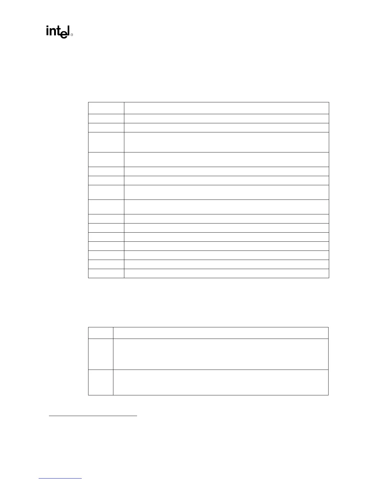
11.1.27 LPC Enables (Function 0)
Address: E6-E7h
Default Value: 0000h
Attributes: Read/Write
11.1.27.1 Firmware Hub (FWH) Decode Enable Register
Address: E3H
Default Value: 00H
1
Attributes: Read/Write
Bit Description
15 Reserved. This bit must be a “0”.
14:13 Reserved.
12 Secondary Configuration Enable: Enables I/O locations 4Eh and 4Fh to be sent to the LPC
bus. Super I/Os use these addresses as an alternate index/data register pair for Super I/O
configuration.
11 Configuration Enable: Enables I/O locations 2Eh and 2Fh to be sent to the LPC bus. Super
I/Os use these addresses as an index/data register pair for Super I/O configuration.
10 ACPI µController Enable: This enables decoding of the ports 62h and 66h to the LPC Bus.
9 MSS Enable: This enables decoding of the Microsoft Sound System range to the LPC Bus.
8 Keyboard Enable: This enables decoding of the keyboard ports at 60h and 64h to the LPC
Bus.
7 Game Port Enable: This enables decoding of the Game Port range at 200h - 20Fh to the
LPC Bus.
6 ADLIB Enable: This enables decoding of the ADLIB range at 388h - 38Bh to the LPC Bus.
5 MIDI Enable: This enables decoding of the MIDI range to the LPC Bus.
4 SB16 Enable: This enables decoding of the SB16 range to the LPC Bus.
3 FDD Enable: This enables decoding of the FDD range to the LPC Bus.
2 LPT Enable: This enables decoding of the LPT range to the LPC Bus.
1 COM B Enable: This enables decoding of the COMB range to the LPC Bus.
0 COM A Enable: This enables decoding of the COMA range to the LPC Bus.
1. LFRAME is defined to be tri-stated at reset. This pin is sampled on PWROK. If the pin is sampled as a logic ‘1’, the firmware does not exist, and
all the registers defined by E3H are cleared to ‘0’. If the pin is sampled as a logic ‘0’, then the firmware does exist, and all the bits in E3H are set
to ‘1’.
Bit Description
7 FWH_F8_EN: This enables decoding of 512 KB of the FWH memory range starting at 4 GB – 512
KB (FFF80000H) to the top 4 GB (FFFFFFFFH). In addition, the upper 128 KB of this range is
shadowed at the top of 1MB (000E0000H – 000FFFFFH). Additionally, this enables decoding of
512K of register space starting at (4 GB – 4 MB) - 512KB (FFB80000h) to the top 4 GB – 4 MB
(FFBFFFFFh).
6 FWH_F0_EN: This enables decoding 512 KB of the FWH memory range starting at 4 GB – 1 MB
(FFF00000H) to 4 GB – 512 KB (FFF7FFFFH). Additionally, this enables decoding of 512K of
register space starting at (4 GB – 4 MB) - 1MB (FFB00000h) to (4 GB – 4 MB) - 512KB
(FFB7FFFFh).