Contents
xi
5 Intel NUC Kit Features ........................................................................................... 61
5.1 Chassis Front Panel Features .............................................................................................................. 61
5.2 Chassis Rear Panel Features ................................................................................................................ 62
Figures
Figure 1. Major Board Components (Top) ....................................................................................................... 15
Figure 2. Major Board Components (Bottom) ................................................................................................ 16
Figure 3. Block Diagram ........................................................................................................................................... 18
Figure 4. 4-Pin 3.5 mm (1/8 inch) Audio Jack Pin Out ............................................................................... 24
Figure 5. LAN Connector LED Locations........................................................................................................... 26
Figure 6. Thermal Solution and Fan Header ................................................................................................... 28
Figure 7. Location of the Standby Power LED ............................................................................................... 33
Figure 8. CEC Connector ......................................................................................................................................... 34
Figure 9. Front Panel Connectors, Controls and Indicators ..................................................................... 38
Figure 10. Back Panel Connectors ...................................................................................................................... 38
Figure 11. Headers and Connectors (Top) ....................................................................................................... 39
Figure 12. Connectors and Headers (Bottom) ............................................................................................... 40
Figure 13. Connection Diagram for Front Panel Header (2.0 mm Pitch) ...... Error! Bookmark not
defined.
Figure 14. Location of the CIR Sensor ............................................................................................................... 43
Figure 15. Location of the BIOS Security Jumper ........................................................................................ 44
Figure 16. Board Dimensions ................................................................................................................................ 46
Figure 17. Board Height Dimensions ................................................................................................................. 47
Figure 18. Localized High Temperature Zones ............................................................................................. 49
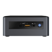
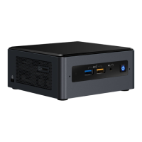
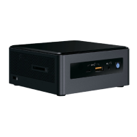
Figure 19. Intel® NUC Products NUC8i5INH/NUC8i7INH Features – Front ....................................... 61
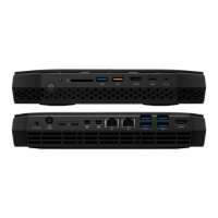
Figure 20. Intel® NUC Products NUC8i5INH/NUC8i7INH Features – Rear ......................................... 62
Tables
Table 1. Feature Summary ..................................................................................................................................... 13
Table 2. Components Shown in Figure 1 ......................................................................................................... 15
Table 3. Components Shown in Figure 2 ......................................................................................................... 17
Table 4. LAN Connector LED States ................................................................................................................... 26
Table 5. Effects of Pressing the Power Switch ............................................................................................... 29
Table 6. Power States and Targeted System Power ................................................................................... 30
Table 7. Wake-up Devices and Events .............................................................................................................. 31
Table 8. HDMI 1 CEC expected behavior.......................................................................................................... 33
Table 9. Headers and Connectors Shown in Figure 11 .............................................................................. 39
Table 10. Connectors and Headers Shown in Figure 12 ........................................................................... 41
Table 11. SATA Power Header (0.5 mm Pitch) .............................................................................................. 41
Table 12. Single-Port Internal USB 2.0 Headers (1.25 mm Pitch) ......................................................... 42
Table 13. Consumer Electronics Control (CEC) Connector (1.25 mm Pitch) .................................... 42
Table 14. SDXC Card Reader Connector .......................................................................................................... 42
Table 15. BIOS Security Jumper Settings ........................................................................................................ 45
 Loading...