EasyManuals Logo

Intel S1400SP User Manual

Intel S1400SP
186 pages
To Next Page IconTo Next Page
To Previous Page IconTo Previous Page
Page #19 background imageLoading...
Page #19 background image
Intel® Server Board S2600IP and Intel® Workstation Board W2600CR TPS Product Overview
Revision 1.1 5
Intel order number G34153-003
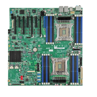
2.1.1 Main Board Connector and Component Layout
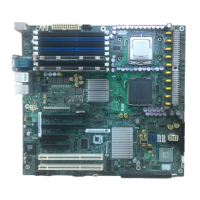
The following figure shows the layout of the server board. Each connector and major component
is identified by a number or letter, and a description is given below the figure.
Callout
Description
Callout
Description
A
Slot 1, PCI Express* Gen3
AD
DIMM C1/C2/D1/D2
B
RMM4 lite module connector
AE
System Fan connector 1/2/3/4/5/6
C
Slot 2, PCI Express* Gen3
AF
Type A USB connector
D
TPM
AG
Type A USB connector
E
Slot 3, PCI Express* Gen3
AH
ROC Module connector
F
Slot 4, PCI Express* Gen3
AI
LCP connector
G
RMM4 Connector
AJ
Front Panel connector
H
Slot 5, PCI Express* Gen3
AK
Front Panel USB connector
I
Battery
AL
Main Power 4-pin connector
J
Slot 6, PCI Express* Gen3
AM
MinISAS Port B(4-7)
K
Slot 7, PCI Express* Gen3
AN
MiniSAS Port A(0-3)

Table of Contents

Other manuals for Intel S1400SP

Questions and Answers:

Question and Answer IconNeed help?

Do you have a question about the Intel S1400SP and is the answer not in the manual?

Intel S1400SP Specifications

General IconGeneral
BrandIntel
ModelS1400SP
CategoryMotherboard
LanguageEnglish

Related product manuals