As the encoder disk rotates between
the emitter and detectors, the light
beam is interrupted by the pattern of
“bars” and “windows” on the disk,
resulting in a series of pulses received
by the detectors.
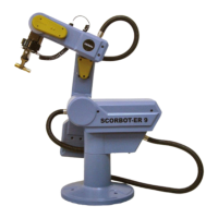
The SCORBOT-ER IX encoders have
512 slots, as shown in Figure 7-2. An
additional slot on the encoder disk is
used to generate an index pulse
(C-pulse) once for each full rotation of
the disk. This index pulse serves to
determine the home position of the axis.
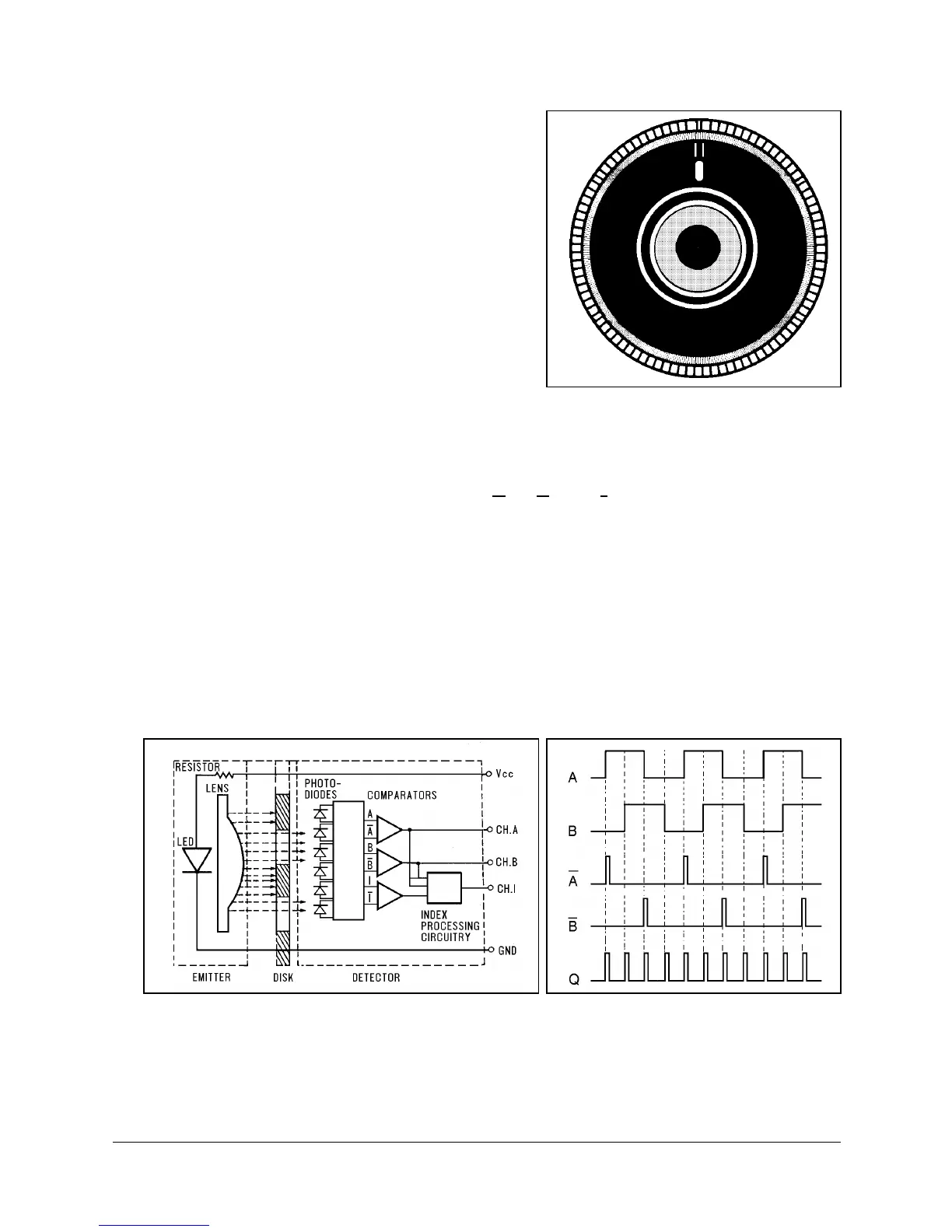
The photodetectors are arranged so that,
alternately, some detect light while
others do not. The photodiode outputs are then fed through the signal processing
circuitry, resulting in the signals A, A, B, B, I and I, as shown in Figure 7-3.
Comparators receive these signals and produce the final digital outputs for
channels A, B and I. The output of channel A is in quadrature with that of
channel B (90° out of phase), as shown in Figure 7-4. The final output of channel
I is an index pulse.
When the disk rotation is counterclockwise (as viewed from the encoder end of
the motor), channel A will lead channel B. When the disk rotation is clockwise,
channel B will lead channel A.
Figure 7-2:
SCORBOT-ER IX Encoder Disk
Figure 7-3: Encoder Circuitry Figure 7-4: Encoder Output Signals
SCORBOT-ER IX 7 - 2 User’s Manual
9603