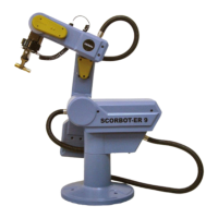
Gripper Installation
The gripper is attached to the flange at the end
of the robot arm whose layout is shown in
Figure 4-5.
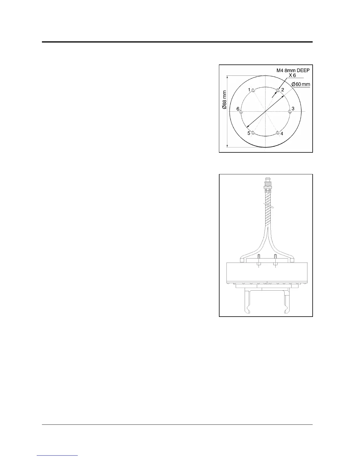
Pneumatic Gripper
The pneumatic gripper, shown in Figure 4-6,
is controlled by a 5/2 solenoid pneumatic
valve which is activated by one of the
controller’s relay outputs. The valve may be
12VDC or 24VDC and can draw its power
from the controller’s User Power Supply.
)
The robot must be homed before you mount the
gripper.
1. Using a hex wrench and six M4x8 socket
screws, attach the gripper to the robot arm
flange.
2. Connect the coiled double hose from the
gripper to the quick coupling on the robot’s
forearm, as indicated in Figure 4-7.
3. Refer to Figure 4-8.
•
Connect the two transparent 1/4" O.D.
hoses from the robot cable to the CYL
ports on the pneumatic valve.
•
Connect a 5 bar/90 PSI air supply to the
IN port on the valve.
4. Refer to Figure 4-9.
Connect the valve to the controller’s User
Power Supply as follows:
•
Connect the black wire to a common terminal.
•
Connect the red wire to the normally open (NO) terminal of any unused relay
output.
5. Connect 12VDC or 24VDC (in accordance with your valve’s specification) to the
common (C) terminal of the same relay output, as shown in Figure 4-9.
Figure 4-5: Gripper Mounting
Flange Layout
Figure 4-6:
Pneumatic Gripper
User’s Manual 4 - 5 SCORBOT-ER IX
9603