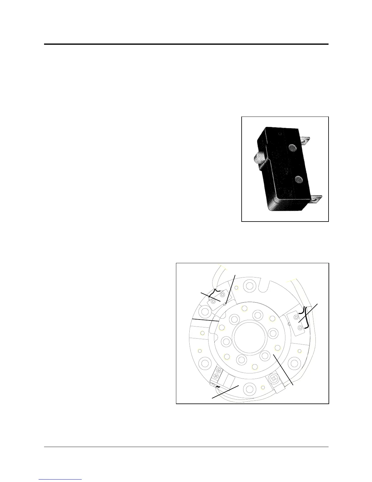
End of Travel (Limit) Switches
The SCORBOT-ER IX uses limit switches to prevent the joints from moving
beyond their functional limits. When a control error fails to stop the axis at the
end of its working range, the limit switch serves to halt its movement. The switch
is part of an electric circuit within the robot arm, independent of the robot
controller.
The limit switches used in the SCORBOT-ER IX are
shown in Figure 7-5.
Each of axes 1 through 4 has two limit switches:
one at each end of the axis’ working range.
Axis 5 (roll) has no travel limit switches; it can
rotate endlessly. When a gripper is attached to axis
5, its movements are controlled and limited by
means of software only (encoder).
The limit switches are mounted on a disk which is
attached to the robot’s frame. The disk for axis 3 is
shown in Figure 7-6.
The output shaft of the Harmonic Drive moves
relative to the microswitch disk.
As the joint moves, a cam
on the Harmonic Drive
output shaft reaches a point
at which it forces the
actuating button of the limit
switch into a position which
activates the switch.
Figure 7-5:
SCORBOT-ER IX
Limit Switch
CAM
LIMIT SWITCH
DISK
HARMONIC
DRIVE OUTPUT
LIMIT
SWITCH
LIMIT
SWITCH
ACTUATING
BUTTON
Figure 7-6: Limit Switch Activation
SCORBOT-ER IX 7 - 4 User’s Manual
9603