Encoder Cable and Connector
The encoder cable, which connects the controller to
the motor encoders and optical home switches,
contains 36 leads.
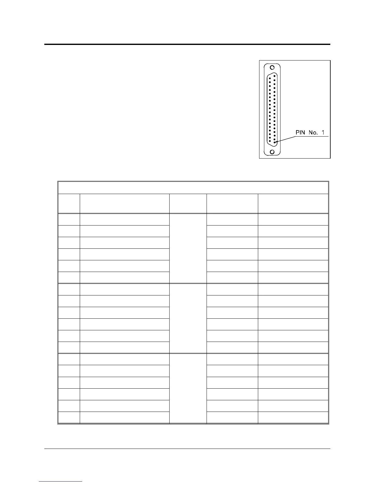
Figure 8-3 shows the D37 female connector that joins
the encoder cable to the controller’s back panel.
The following table details the connector pin functions
and describes the cable wiring.
Encoder Cable and D37 Connector
Pin
ID
Pin Description
Robot Side (J1)
Axis
Telephone
Cable Color
Pin Description
Controller Side (J2)
1+5V
1
red +5V
8 COMMON yellow COMMON 0
5 CHA1 (Encoder Pulse A) green CHA 0
6 CHB1 (Encoder Pulse B) white CHB 0
7 CHC1(Encoder Index Pulse) black CHC 0
31 MSWITCH (Home Switch) blue MSWITCH
1+5V
2
red +5V
12 COMMON yellow COMMON 1
9 CHA2 (Encoder Pulse A) green CHA 1
10 CHB2 (Encoder Pulse B) white CHB 1
11 CHC2 (Encoder Index Pulse) black CHC 1
32 MSWITCH (Home Switch) blue MSWITCH
1+5V
3
red +5V
16 COMMON yellow COMMON 2
13 CHA3 (Encoder Pulse A) green CHA 2
14 CHB3 (Encoder Pulse B) white CHB 2
15 CHC3 (Encoder Index Pulse) black CHC 2
33 MSWITCH (Home Switch) blue MSWITCH
Figure 8-3:
D37 Connector
User’s Manual 8 - 3 SCORBOT-ER IX
9603