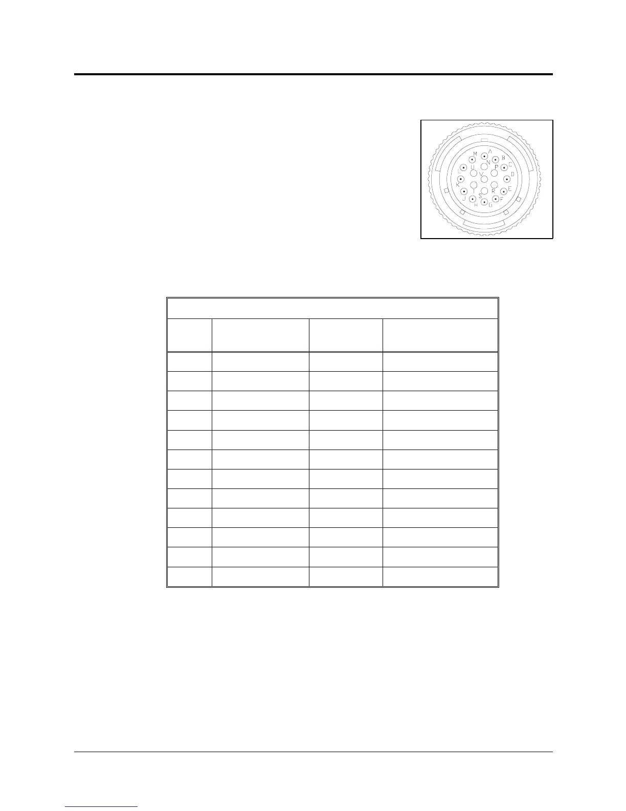
Robot (Power) Cable and Connector
Figure 8-2 shows the Burndy 19 pin male connector
that joins the power cable to the controller’s back
panel.
The robot cable contains 12 leads. The following
table details the connector pin functions and cable
wiring.
Robot (Power) Cable Wiring and Connector
Pin
ID
Pin Description
Robot Side (J1)
Beldan
Color
Pin Description
Controller Side (P1)
A Motor 1 – black M0_A
M Motor 1 + red M0_B
C Motor 2 – brown M1_A
L Motor 2 + orange M1_B
E Motor 3 – yellow M2_A
H Motor 3 + purple M2_B
B Motor 4 – light blue M3_A
K Motor 4 + blue M3_B
D Motor 5 – grey M4_A
J Motor 5 + pink M4_B
F Motor 6 – white M5_A
G Motor 6 + green M5_B
Figure 8-2: Burndy 19 Pin
Connector
SCORBOT-ER IX 8 - 2 User’s Manual
9603