CHAPTER
8
Wiring
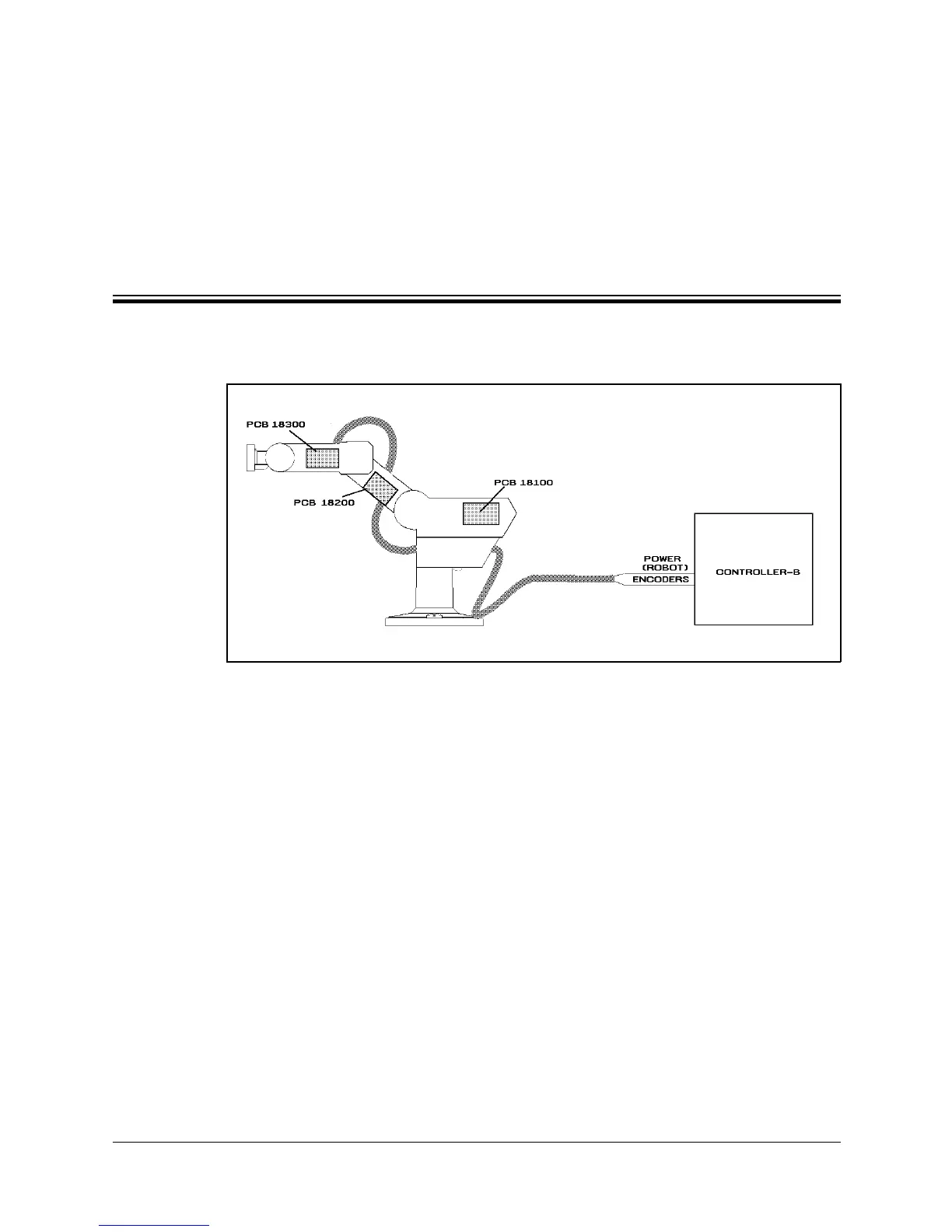
Figure 9-1 is a schematic diagram of the SCORBOT-ER IX cable connections.
The wire braid which connects the robot to the controller contains a power (robot)
cable and an encoder cable.
The body, upper arm and forearm links each contain a printed circuit board
(PCB). The motors, encoders, limit switches and home switches for each axis are
directly connected to one of these three internal PCBs. Two wire braids connect
the PCBs. Each PCB transfers power to the motors to which it is directly
connected, and receives signals from the corresponding limit and home switches.
When a limit switch is triggered, the PCB automatically cuts off power to the
motor that drives the axis. In addition, each PCB transfers power to the next PCB
and sends encoder and home switch signals to the previous PCB.
The robot and encoder cable are directly connected to PCB 18100. The robot
cable supplies power to the PCB and the encoder cable carries information from
the encoders and the home switches for all six axes to the controller.
Figure 8-1: SCORBOT-ER IX Cabling
User’s Manual 8 - 1 SCORBOT-ER IX
9603