OW50M - OneWeb Maritime Antenna System
16
4.2 Selecting Installation Site
The mounting location and mounting post must be robust enough that it will not flex or sway in ship motion
and well re-enforced to prevent flex and vibration forces from being exerted on the antenna and radome.
The mounting post must also be rigid enough to withstand the forces exerted by full rated wind load on the
radome.
4.2.1 Installation Location for Antenna
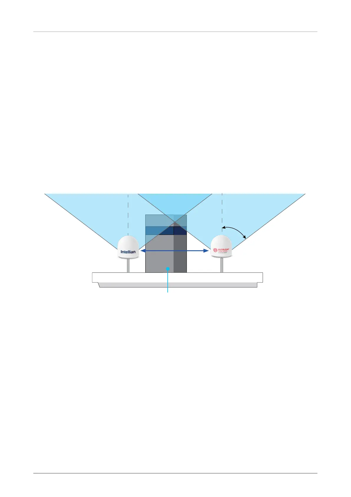
For optimal performance, it is preferable that the user terminal has an unobstructed view of the horizon
or satellite in all directions. Although the user terminal itself can mitigate blockages, it is ideal to have no
obstacles within a 53-degree range from the zenith (or 78 degrees if considering a ship in motion).
To utilize the basic antenna system, two antennas must be installed with a minimum distance of 3.5 meters
(11.5 feet) between them to facilitate blockage mitigation.
During antenna installation, it is essential to input the values of every blockage zone, including elevation and
azimuth angles, in the “configure blockage zones” for seamless blockage mitigation. Intellian recommends
following these guidelines for best results.
Obstruction
Field of View
3.5 m (11.5 ft)
Figure 1: Minimizing Satellite Blockage (example)
4.2.2 Installation Location for CNX
An ideal location for the CNX should be:
• The room climate controlled.
• Adequate ventilation on each side of the rack
• Adequate room behind the rack
• Within 30 m (98 ft) of the antennas with RG6 coax cable
• Within 100 m (328 ft) of the antennas with RG11 coax cable
• Within 1.5m from AC Power Source (100-240 VAC, 50-60 Hz)

 Loading...