33
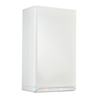
Assembly of combi-pipe horizontal terminal
► Create an opening of Ø130 mm at the location of the
terminal.
► Shorten the combi-pipe wall terminal to the indicated
length.
► Assemble the outlet grille and attach this to the internal
pipe.
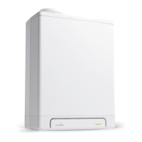
► Slide the combi-pipe wall terminal in the opening and
attach rosettes to cover the opening.
► Assemble the combi-pipe wall terminal to the boiler at an
angle.
COMMENT
► Pipes for the connection of the air supply
duct and the flue between the boiler and
the combi-pipe wall terminal must have a
diameter of Ø80 mm.
► It is recommended to use a flue gas non
return valve.
► The individual flue pipe (Ø80) and/
or the internal pipe of the combi-pipe
wall terminal / extension pipe must be
constructed of stainless steel or PP T120.
Allowed pipeline length
► Twin-pipe
Air supply duct and flue pipe together, excluding the length of
the combi-pipe wall terminal.
Boiler Length
Intergas Xtreme 24 100 m
Intergas Xtreme 30 85 m
Intergas Xtreme 36 80 m
► Concentric
Air supply duct and combustible gas exhaust pipe
together, excluding the length of the combi-pipe wall
terminal.
125
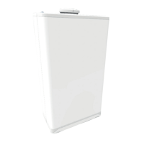
6.8.2 Façade combi-pipe horizontal terminal C13
Boiler C13
Ø60/100
Intergas Xtreme 24 10 m
Intergas Xtreme 30 10 m
Intergas Xtreme 36 10 m
Boiler C13
Ø80/125
Intergas Xtreme 24 29 m
Intergas Xtreme 30 29 m
Intergas Xtreme 36 29 m