Chapter 2: Installation
TruVision DVR 12 User Manual 5
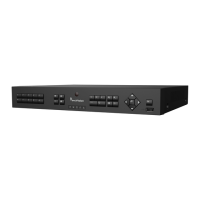
Figure 1: TVR 12 back panel connections (16-channel model shown)
1. Loop through for up to 16 analog cameras
(depends on DVR model).
2. Connect to a RS-232 device.
3. Connect up to four alarm inputs and one
alarm output.
4. Connect one alarm relay output.
5. Connect four audio inputs to RCA
connectors.
6. Connect up to 16 analog cameras to BNC
connectors (depends on model of DVR).
7. Connect to an optional USB device such as
a mouse, CD/DVD burner or HDD. The
DVR supports both a USB DVD and a USB
8. Connect one CCTV monitor (CVBS
connector).
9. Connect to a HDTV. The HDMI connection
supports both digital audio and video.
10. Connect to a VGA monitor.
11. Connect to speakers for audio output.
12. Connect to a network.
13. Connect to a RS-485 device such as a PTZ
camera or a keypad.
14. Connect to the PSU (12 VDC).
15. Power switch (on/off).
16. Connect to ground.
Monitor connections
Connect a monitor to one of the DVR’s outputs (BNC/VGA/HDMI). The DVR
provides a 1 Vp-p CVBS signal. See Figure 1 above for connecting a monitor to a
DVR.
The DVR supports up to 1280 × 1024 / 60 Hz resolution in VGA. The monitor
resolution should be at least 800 × 600. Adjust your monitor accordingly to this
resolution.