The FT Series Floor Standing, Heating Only Boiler
Page 21
4.8 Air Supply and Vent Connections
4.8.2 Direct Venting
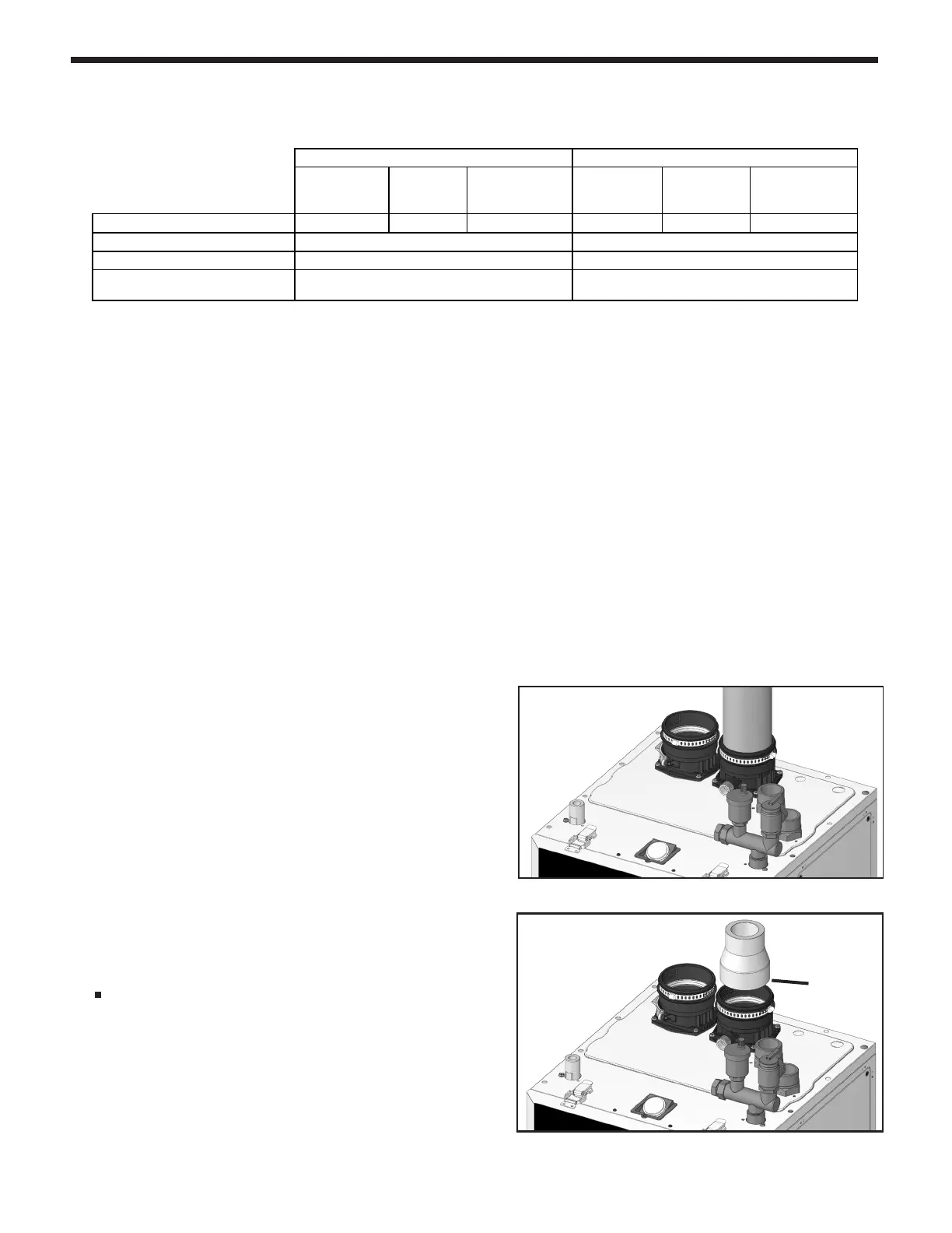
The FT boiler uses 3˝ or 2˝ diameter exhaust and 3˝ or
2˝diameter intake air ducts. To ensure the draw of air
directly from and exhaust of air directly to the outside of
the building, create an airtight seal from the boiler collar
to the vent termination.
(For installations in Canada) eld-supplied plastic
vent piping must comply with CAN/CSA B149.1 (latest
edition) and be certied by the Standard For Type BH
Gas Venting Systems, ULC-S636. Components of
this listed system must not be interchanged with other
vent systems or unlisted pipes or ttings. All plastic
components and specied primers and glues of the
certied vent system must be from a single system
manufacturer and must not be intermixed with another
system manufacturer’s parts.
Tightening — Boiler Collar (Socket) to Vent Pipe &
Inlet Pipe
- Clean and dry your selected PVC, CPVC vent pipe
and boiler collar (socket).
- Push the pipe into the collar (socket) until it touches
the bottom of the socket tting.
- For 2” installations, install a eld supplied 3” to 2”
adaptor. Adaptor must be installed in vertical section of
piping only.
Table 5. Maximum Vent / Air Pipe Lengths for either 3” or 2 “ Pipes
(PVC schedule 40, CPVC schedule 40, SS, PP)
2” pipe connected, using an adapter
3” to 2”
adapter
is NOT
included.
3” pipe
4.8.1 Vent / Air Pipe Lengths for dual pipe venting systems.
Use this table for Doc. 1483
Min.
Combustion Air
Pi
e
Min. Vent
Pipe
Max. Combustion
Air & Vent Pipe
Min.
Combustion
e
Min. Vent
Pipe
Max. Combustion
Air & Vent Pipe
MFTHW 100/140/199 NG & LP
0 FT
* (0 M)
3 FT (1 M) 50 FT (15 M)
0 FT* (0 M)
3 FT (1 M) 100 FT (30 M)
Deductions per 90° Elbow
Deductions per 45° Elbow
Max. # of Total Elbows on
ir Intake & Exhaust Vent
**When using 2" Combustion Air & Vent pipe, Propane Models are limited to 25 equivalent feet (7.5 M) of vent and 25 equivalent feet (7.5 M) of combustion a
Use this table for Doc. 1487
Min.
Combustion Air
Pi
e
Min. Vent
Pipe
Max. Combustion
Air & Vent Pipe
Min.
Combustion
ir Pi
e
Min. Vent
Pipe
Max. Combustion
Air & Vent Pipe
MFTCW 140/199 NG & LP
0 FT
* (0 M)
3 FT (1 M) 50 FT (15 M)
0 FT* (0 M)
3 FT (1 M) 100 FT (30 M)
Deductions per 90° Elbow
Deductions per 45° Elbow
Max. # of Total Elbows on
ir Intake & Exhaust Vent
**When using 2" Combustion Air & Vent pipe, Propane Models are limited to 25 equivalent feet (7.5 M) of vent and 25 equivalent feet (7.5 M) of combustion a
46
*appliance needs to vent outdoors using approved vent caps and following all
guidelines as noted in our IO manual.
Proper protection against debris in the air intake (through using a downward spout
and/or screen) to avoid debris pick-up / falling into the appliance is required.
*appliance needs to vent outdoors using approved vent caps and following all
guidelines as noted in our IO manual.
Proper protection against debris in the air intake (through using a downward spout
and/or screen
2" Combustion Air & Vent Pipe 3" Combustion Air & Vent Pipe
8 FT (2.4 M) 5 FT (1.5 M)
4 FT (1.2 M) 2.5 FT (.75 M)
2" Combustion Air & Vent Pipe 3" Combustion Air & Vent Pipe
64
8 FT (2.4 M)
4 FT (1.2 M)
5 FT (1.5 M)
2.5 FT (.75 M)
NOTES:
• One must include all elbows on the air intake and exhaust piping in determining the maximum equivalent
length of the air intake and exhaust vent piping.
• A total of 4 elbows matches the total number of elbows allowed for 2” venting.
Example: 2” venting system desired.
Air intake piping: Two 90 elbows and 15 ft of straight pipe: 2 x 8 ft + 15 ft = 31 ft (okay)
Exhaust vent piping: Two 90 elbows and 20 ft of straight pipe: 2 x 8 ft + 20 ft = 36 ft (okay)
NOTE: Proper protection against debris in the air intake (through using a downward spout and/or screen) to
avoid debris pick-up / falling into the appliance is required.
* Appliance needs to vent outdoors using approved vent caps and following all guidelines as noted in the
Installation Manual.
FTHF 199 NG & LP