Page 48
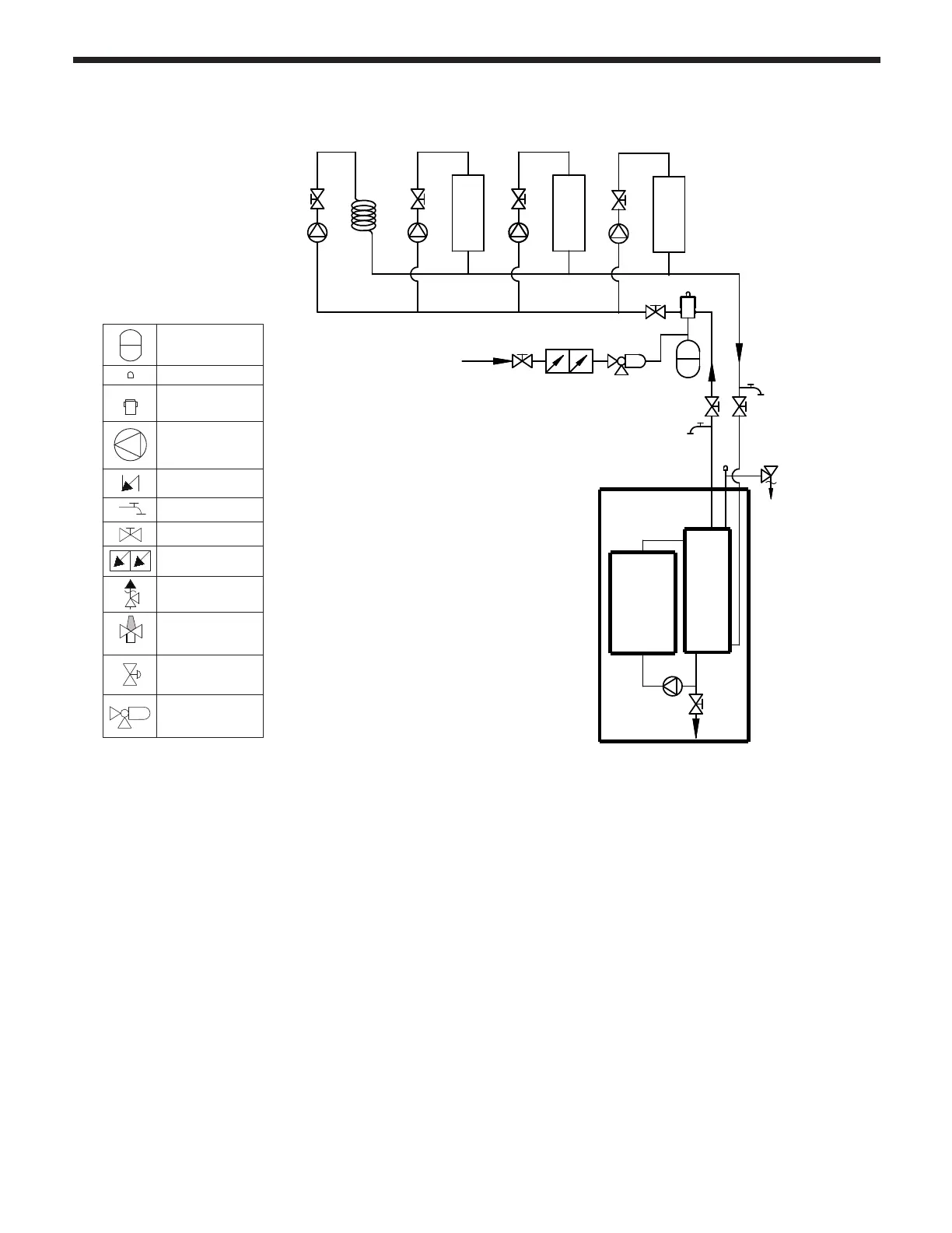
4.16.6 Zoning with pumps and indirect DHW tank pump.
1. This piping diagram is meant to show system piping concept only. Installer is responsible for all
equipment and detailing required by local codes.
2. The minimum size piping to the Indirect Tank heat exchanger is ¾” inside diameter.
3. Install a minimum of 12 diameters of straight pipe upstream of all circulators.
4. The system return must be piped directly to the Boiler Return connection.
5. The system supply must be piped directly to the Boiler Supply connection.
6. The heat exchanger in the Indirect Tank shall be piped as a separate zone. Power the pump
for the indirect tank from the DHW tank terminals. The (dry contact) aquastat or DHW sensor
connects back to the DHW sensor terminals of the boiler.
7. Manufacturer strongly recommends the use of an anti-scald mixing valve at the hot water outlet
of the Indirect Tank to reduce the potential for scalding. Check with local codes.
(FACTORY
WIRED)
LLH
ZONE 2
MFTHF Multizone Heating w Circulators & Indirect Tank
ZONE 3
MAKE UP
WATER
ZONE 1
INDIRECT H-X
A
B
EXPANSION
TANK
BACKFLOW
PREVENTER
PURGE
VALVE
AIR
ELIMINATOR
CHECK
VALVE
ISOLATION
VALVE
REDUCING
PRESSURE
VALVE
AIR
VENT
CIRCULATOR
RELIEF
T & P
VALVE
E
B
O
I
L
R
Circulation pump
Check valve
Zone valve
Pressure
reducing valve
Drain valve
Gate valve
Backflow preventer
Pressure Relief Valve
Expansion tank
Air separator
(Diaphragm-type)
Automatic air vent
Anti-scald rated
Mixing Valve
Check Valve
Shut-off valve
Circulation pump
with built-in IFC