Page 26
4.10.2 Installation of a Complete New Concentric
Stainless Steel Venting System.
For a vertical venting system, locate the boiler to aect
the shortest possible vent length run with the
maximum venting length not to exceed 25 feet and no
more than 3 90° elbows.
Venting Assembly Process:
Note:
Follow the detailed instructions supplied with
the Heat-Fab SC series venting components during
the assembly process.
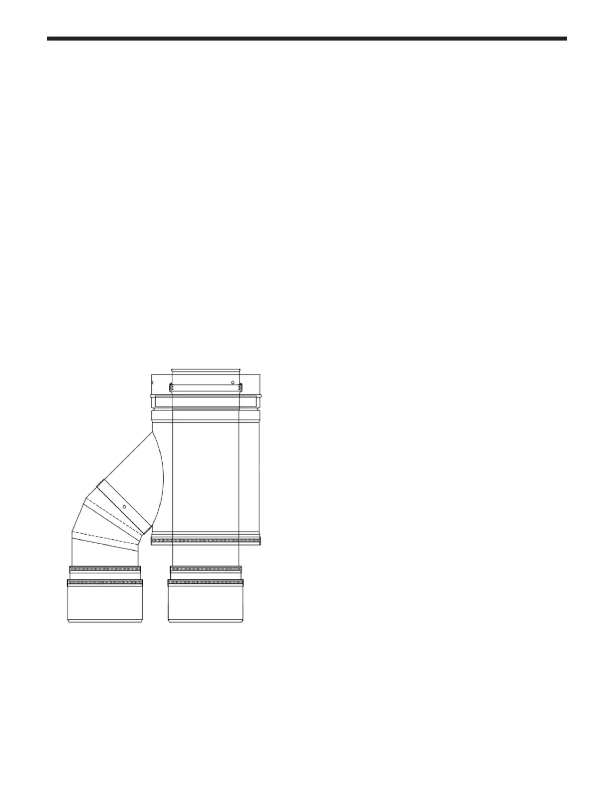
1)
Install the Dual pipe to concentric adaptor, kit
FT3006. Ensure that the ttings are clean, moisten the
seals and pipe ends before insertion and insert the
Dual pipe to concentric adaptor, kit FT3006 into the FT
boiler sockets until they bottom out. Tighten the
clamps on the boiler vent connectors.
2)
The venting system will probably have both
horizontal and vertical components to align the Dual
pipe to concentric adaptor, kit FT3006, and the
penetration through the roof.
3)
The selection on the roof for the roof termination
must follow the guidelines of Section 4.9 Vent / Air
Termination, Page 22 in this manual.
4)
Locate the FT boiler as close as possible to the site
of the roof termination overhead and determine the
routing of the venting system and measure the
required lengths of horizontal and vertical runs.
5)
Properly support each horizontal and vertical
section at least every 4 ft and at each elbow. Finish
the vertical section by the installation of the SCO3VT
Vertical Terminal Adapter on the last piece of vertical
concentric vent pipe.. The top of this adapter must be
12” above the roof or anticipated snow line where it
penetrates the roof. Install a SCO3RC, Rain Cap.
6)
After completion of the venting system, review all
joints of the venting installation and make sure that all
locking screws of the adjoining vent sections are all
fully installed into the pre-drilled holes.
For a horizontal venting system do not exceed the
maximum allowed lengths and number of elbows
noted above and select a location for the vent
termination on the outside wall. This location must
consider the 12” height above grade and/or anticipated
snow line and its proximity to windows, doors and
sources of incoming air, etc. Reference Section 4.6
Locations for Vent Pipe Terminator, Page 18 in this
manual.
Venting Assembly Process:
Note:
Follow the detailed instructions supplied with
the Heat-Fab SC series venting components during
the assembly process.
1)
Locate the FT boiler as close as possible to the
selected location for the penetration through the
outside wall and install the Dual pipe to concentric
adaptor, FT3006 kit, in the sockets on the FT boiler.
Ensure that the ttings are clean, moisten the seals
and pipe ends before insertion and insert the Dual
pipe to concentric adaptor, FT3006 kit, into the FT
boiler sockets until they bottom out.
2)
Determine the routing of the venting system and
measure the required lengths of horizontal and vertical
runs. Keep in mind that telescoping pieces may be
required for certain lengths as the pipes can NOT be
trimmed to length. Each vertical and horizontal run
must be supported by hangers every 4 ft so that it
slopes 3/8” per foot downward toward the FT boiler
and has no low sections that will limit the ow of
condensate back to the boiler.
3)
The telescoping sections are used to adjust both
the vertical and the horizontal sections of the pipes so
that the proper slope can be maintained.
4)
Install the 3" x 5" horizontal termination adaptor
(SCO3HT) on the last piece of horizontal concentric
vent pipe protruding through the exterior wall and
select one of the listed horizontal terminations to
complete the concentric venting installation.
FT3006 Kit