Page 76
This controller is able to record information about the boiler’s condition at the time of the ve previous faults or
errors. Refer to the Section ‘5.11 Error Mode’ of this manual.
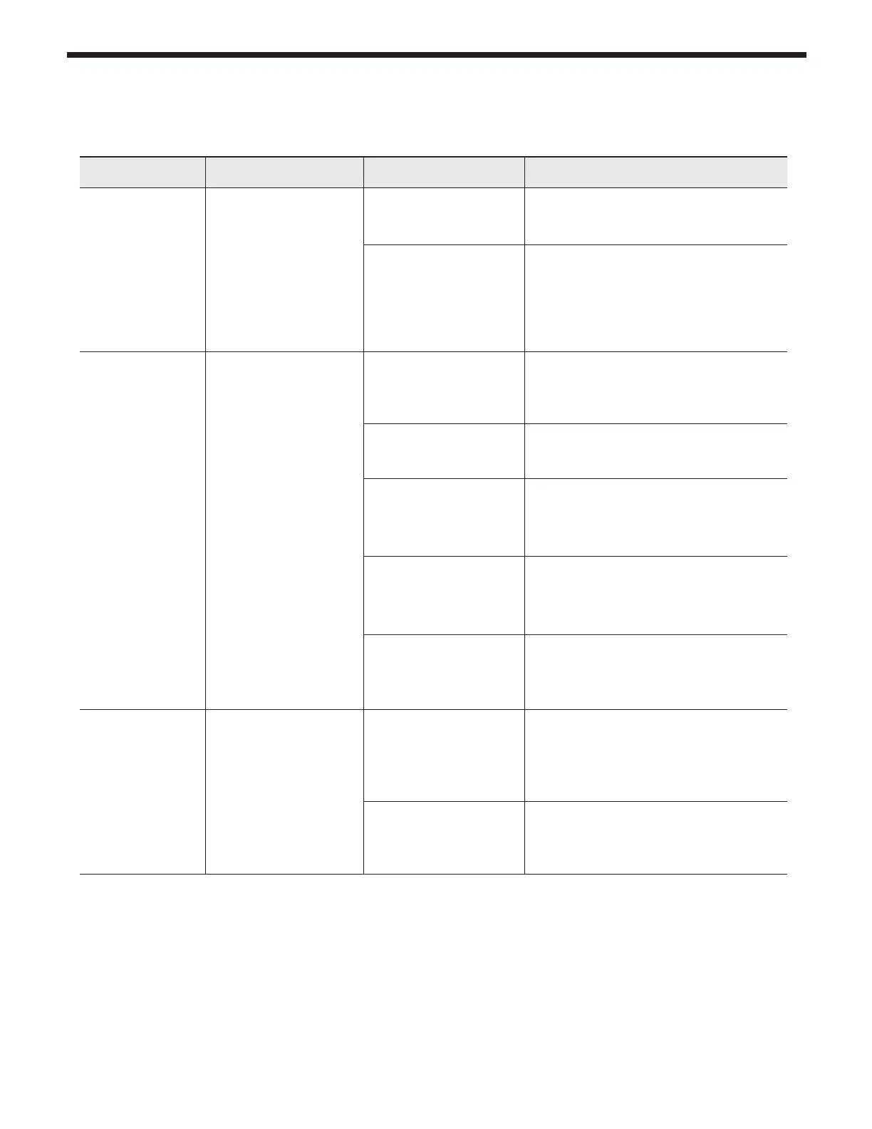
Display Condition Diagnostic Corrective Action(s)
Nothing shown
on display
control panel and
blower running at
full speed.
Control is not
receiving power.
Check wiring for short
circuit or incorrect
wiring.
Correct wiring per wiring diagram
including connection of transformer to
the control.
Check transformer
connection to the
control per wiring
diagram. Check
for 12V output of
transformer.
Replace transformer if it is receiving
120V, but not outputting 12Vac.
Nothing is shown
in display control
panel and no
other boiler
components are
operating.
Control is not
receiving 120V power.
Check service switch
and/or circuit breaker
to boiler turned is on.
Turn on service switch to power boiler.
Is there 120 Volts at
the service switch?
Troubleshoot and correct the power
supply to the manual switch.
Is the ON/OFF
POWER
SWITCH (inside boiler
case) turned on?
Turn ON the manual power switch
inside the boiler case.
Check for 120 volts
at the line voltage
terminal block located
inside the boiler case.
Correct wiring inside the boiler case
using the wiring diagram in this
manual.
Inspect the fuse.
Replace if necessary.
Replace the fuse with proper part
found in the replacement part section
of this manual. If fuse blows again
recheck wiring per diagram.
Nothing is shown
on control panel,
but boiler is
operating.
Occurs when the
communication is lost
from the control to the
display.
Check for loose
connections and
proper pin alignment/
engagement on the
Control's plug.
Check for continuity on the wire
harness from the display to the control.
See repair parts section for proper
replacement part.
Cycle power o and
on using boiler power
switch and check for
operation.
Replace with new display module.
See repair parts section for proper
replacement part.
7.2 Suggested Corrective Actions