The FT Series Floor Standing, Heating Only Boiler
Page 51
1
2 3
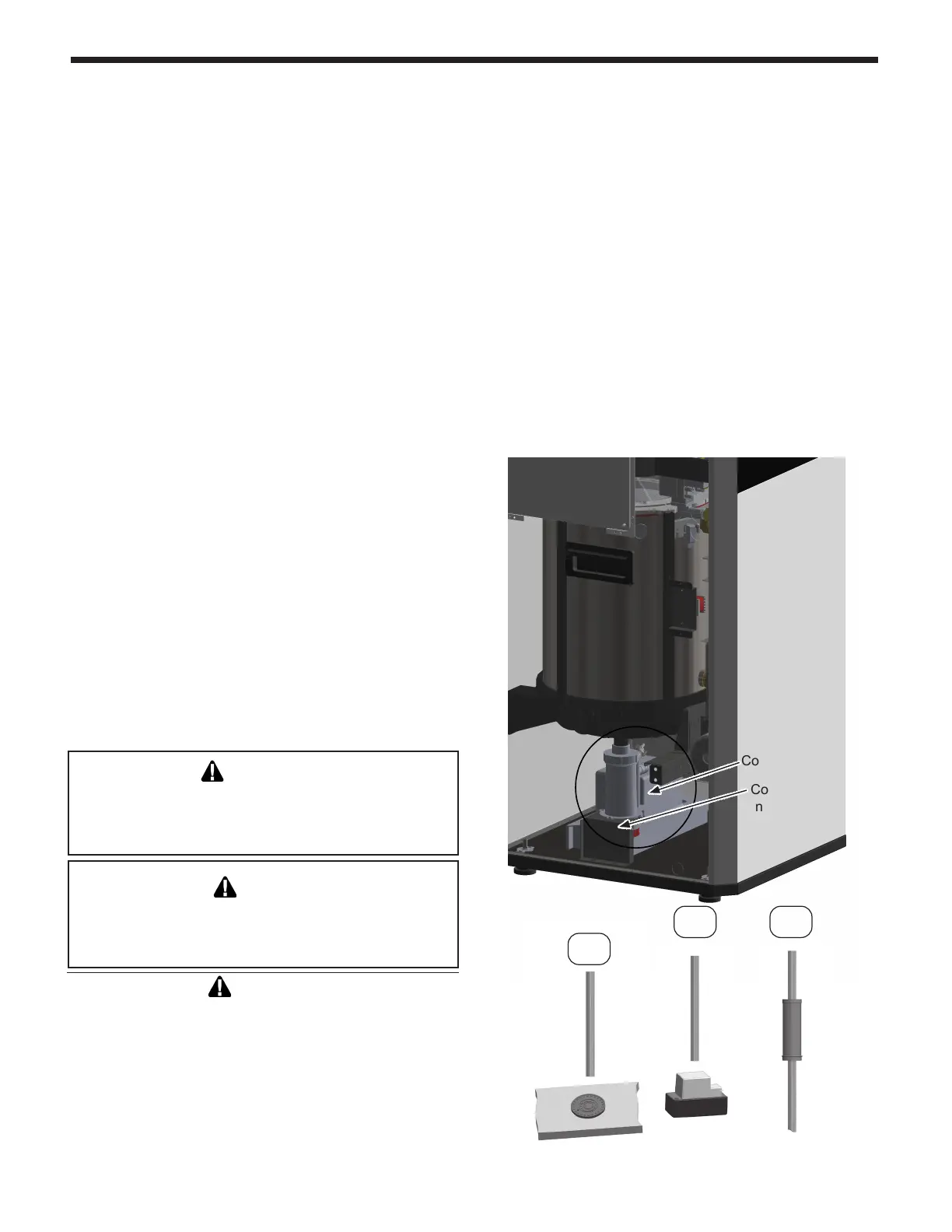
(View is as
if side panel
were removed)
Condensate Trap
Combination
neutralizer/
condensate
pump kit
• High eciency gas condensing boilers create
condensation when operating. Condensation is acidic
with a pH ranging from 4 to 5.
• Attach the supplied condensate drain hose to the
installed condensate trap. Make sure to attach
the 1/8” air vent tube and secure this 6” long hose
to a bracket so it will not spill condensate. Follow
your local code with regards to the disposal of
condensation.
One of 3 disposal methods must be followed
1. to a oor drain
2. Combination neutralizer and condensate pump
kit (optional kit available from manufacturer)
3. to a condensate pump (eld supplied)
• If a neutralizer is installed, periodic replacement of the
lime stone (or neutralizing agent) will be required. The
rate of depletion of the lime stone varies upon usage
of the boiler. During the rst year of operation, please
check the neutralizer every few months for depletion.
• Apply only corrosion-resistant materials for the
condensate drain lines such as 1/2˝ PVC, CPVC,
Polypropylene pipe or included plastic hose.
• In case of a closet installation, a combination
neutralizer/pump (FT3007 kit) can be installed by
removing the lower left access panel, an electrical
outlet (Max amp rating: 2 Amp) is provided to power
the condensate pump.
• Overall dimensions can not exceed 15-7/8” (L) x
5-7/16” (W) x 6-3/4” (H) in order to t inside the
boiler cabinet.
NOTICE
Category II & IV boilers must be installed with a means
provided for the drainage of condensate.
AVIS
les chaudières de catégories II et IV doivent être
installées avec un moyen de drainage du condensat.
CAUTION
Condensate is mildly acidic (pH=5), and may harm
some oor drains and/or pipes, particularly those
that are metal. Ensure that the drain, drainpipe, and
anything that will come in contact with the condensate
can withstand the acidity, or neutralize the condensate
before disposal. Damage caused by failure to install
a neutralizer kit or to adequately treat condensate
will not be the manufacturer’s responsibility.
Various condensate disposal methods
• If desired, a discharge 1/4” or 3/8” can be routed by
removing yellow cap from the top right rear corner
and routing the hose down to the condensate pump.
• Knock-out provisions are supplied in the lower left,
rear or right hand side panels to rout the condensate
to a nearby oor drain or externally placed
condensate pump.
• Cut a small opening in the plastic grommet and pull
the discharge hose through the opening for strain
relief.
• When placing the FT3007 kit or other suitable
condensate pump/ neutralizer combination inside
the cabinet, it may be necessary with a small clip
(not provided) to secure the condensate hose
coming from the trap to this cover. One can also use
the soft plastic insert, shorten the condensate drain
hose and carefully “thread” the hose into this insert
and place it into its designation location of the
FT3007 kit.
4.18 Disposal of Condensate