INSTALLATION
18
3
2
1
interVOLT Model
DCC1225ACD
Battery to Battery
Charging Device
12VDC - 12VDC
25 Amps max.
The negative power cable should be
connected to the Charging Device rst.
This should be fastened to the terminal
marked NEG using the special screw
provided. Connect the other end of the
negative to the main battery negative
(recommended) or directly to the
chassis, ensuring the connection has
good contact. Ensure the auxiliary
battery negative is either connected to
the NEG terminal of the Charging
Device or the chassis.
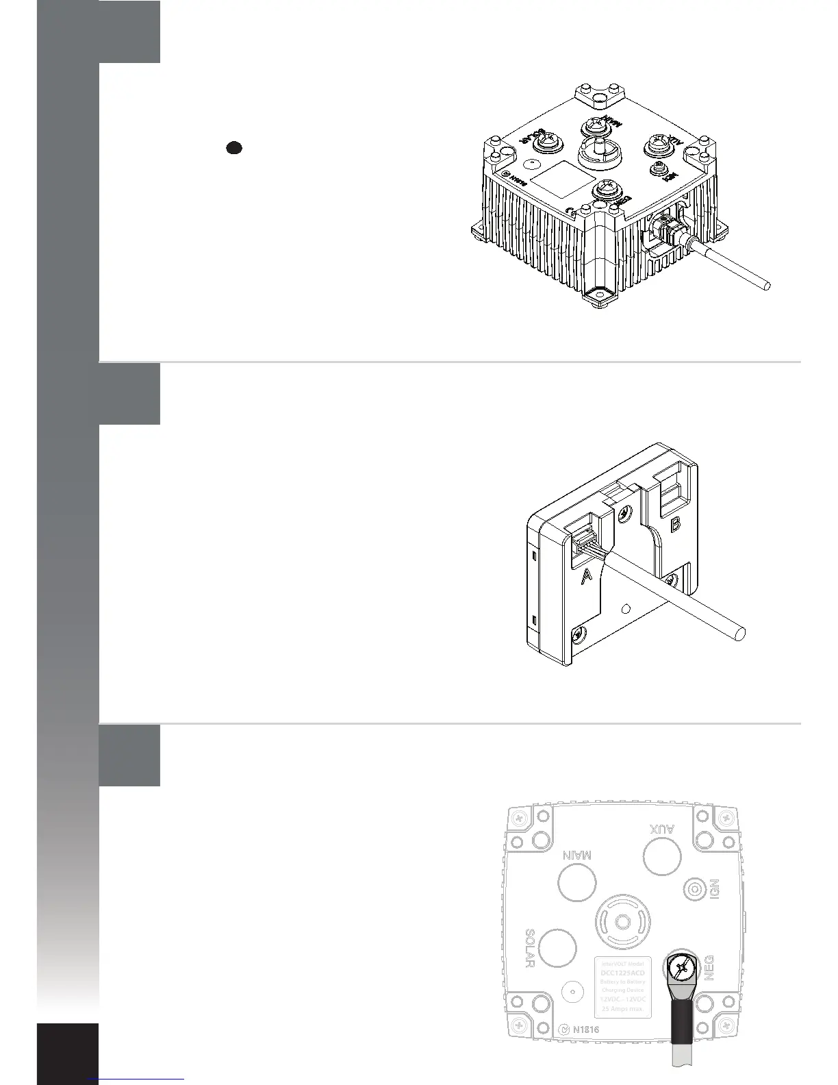
The Remote Display end of the Data Cable
is tted with an unsealed 6-way connector
plug. The plug is tted with a plastic
clamshell to protect it from damage
during installation. The clamshell is
secured with tape and should now be
removed for installation. The plug should
be gently pushed into the mating
connector socket until it ‘clicks’ into
position. When using one Charging Device
either socket can be utilised.
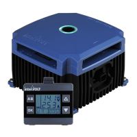
The Charging Device end of the Data
Cable is tted with a sealed 6-way
connector plug. The plug is marked with
a spot of identifying colour indicating
the top of the connector. The plug should
be gently pushed into the mating
connector socket until it ‘clicks’ into
position. To check the latch has engaged
gently pull the connector – it should not
move. If there is a need to remove the
connector, please see page 23 for
instructions.
Connect the negative power cable to the Charging Device
Connect the Data Cable to the Remote Display (if utilised)
Connect the Data Cable to the Charging Device