INSTALLATION
19
6
5
4
interVOLT Model
DCC1225ACD
Battery to Battery
Charging Device
12VDC - 12VDC
25 Amps max.
interVOLT Model
DCC1225ACD
Battery to Battery
Charging Device
12VDC - 12VDC
25 Amps max.
Conguring or ‘setting up’ the Charging Device is the
next step in the sequence. To initiate set-up mode
follow the steps below:
I. Press and hold the button until an audible
‘beep’ is heard and a scrolling message reads
‘To configure press up’. The LED Glow
Ring will now indicate purple intermittently.
II. Release the button.*
III. Press the button to initiate the set-up mode
and continue to next step.
* If an error message is displayed please see page 33.
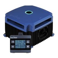
The ignition cable is the next to be
connected, if the intention is to use
Ignition Control Mode (see page 6).
Keep in mind that the control mode
setting is optional and, even if the
ignition wire is connected, it does not
necessarily need to be implemented in
set-up mode.
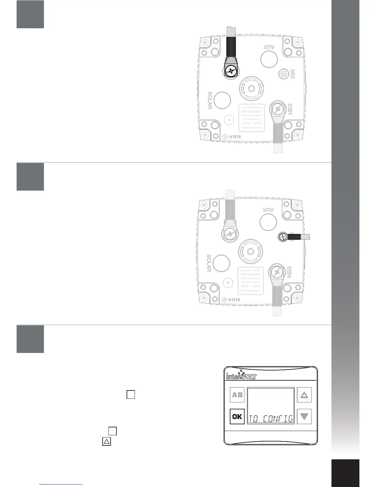
The main positive power cable is the
next to be connected. Check the in-line
fuse is removed prior to connecting the
cable. Connect the Charging Device end
of the positive cable to the terminal
marked MAIN using the special screw
provided. Connect the other end of the
cable to the main battery positive. Insert
the fuse into the inline fuse holder. The
Charging Device is now powered and
the LED indicators should be ashing
white intermittently.
Configure the Charging Device: Initialising set-up mode
Connect the ignition cable to the Charging Device
(if utilised)
Connect the main battery cable to the Charging Device
OK
OK