INSTALLATION
22
15
14
13
interVOLT Model
DCC1225ACD
Battery to Battery
Charging Device
12VDC - 12VDC
25 Amps max.
interVOLT Model
DCC1225ACD
Battery to Battery
Charging Device
12VDC - 12VDC
25 Amps max.
Locate the terminal cover according
to the arrows. The cover is indexed
and must t into the locating pins in
order for the Glow Ring to operate
correctly. The installation is now
complete, however if you have a
second Charging Device to install
please proceed to step 17.
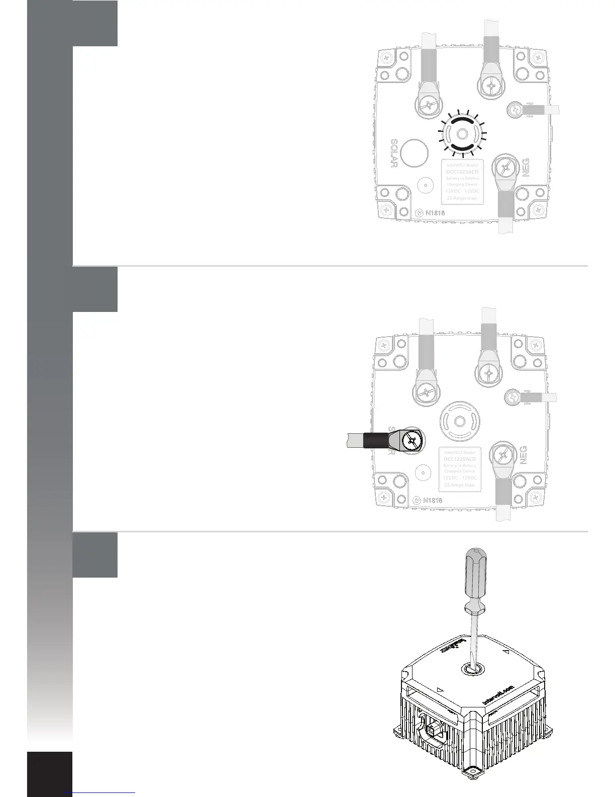
The solar panel positive power cable
can now be connected. Check the
in-line fuse is removed prior to
connecting the cable. Connect the
output positive cable from the solar
panel to the terminal marked SOLAR
using the special screw provided.
Reinstall the fuse into the inline fuse
holder. Subject to the state of the
auxiliary battery, the Charging Device
may enter solar mode. See page 7
for more information. Continue to
next step.
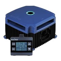
The Charging Device should now be active.
Subject to the state of the main and
auxiliary batteries, the Charging Device will
now enter standby mode or a charging
stage. See pages 6-7 for more information.
As a result the LED indicators will reect the
current stage, for example if the current
stage is ‘oat’ they will illuminate green
continuously. If a solar panel is to be
connected continue to next step.
Otherwise continue to step 15.
Reinstall the terminal cover
Connect the solar panel power cable (if available)
Confirming operation