INSTALLATION
21
interVOLT Model
DCC1225ACD
Battery to Battery
Charging Device
12VDC - 12VDC
25 Amps max.
12
11
10
The auxiliary positive battery cable should
now be connected. Check the in-line fuse
is removed prior to connecting the cable.
Connect the Charging Device end of the
positive cable to the terminal marked AUX
using the special screw provided. Connect
the other end of the cable to the auxiliary
battery positive. Insert the fuse into the
inline fuse holder and continue to next
step.
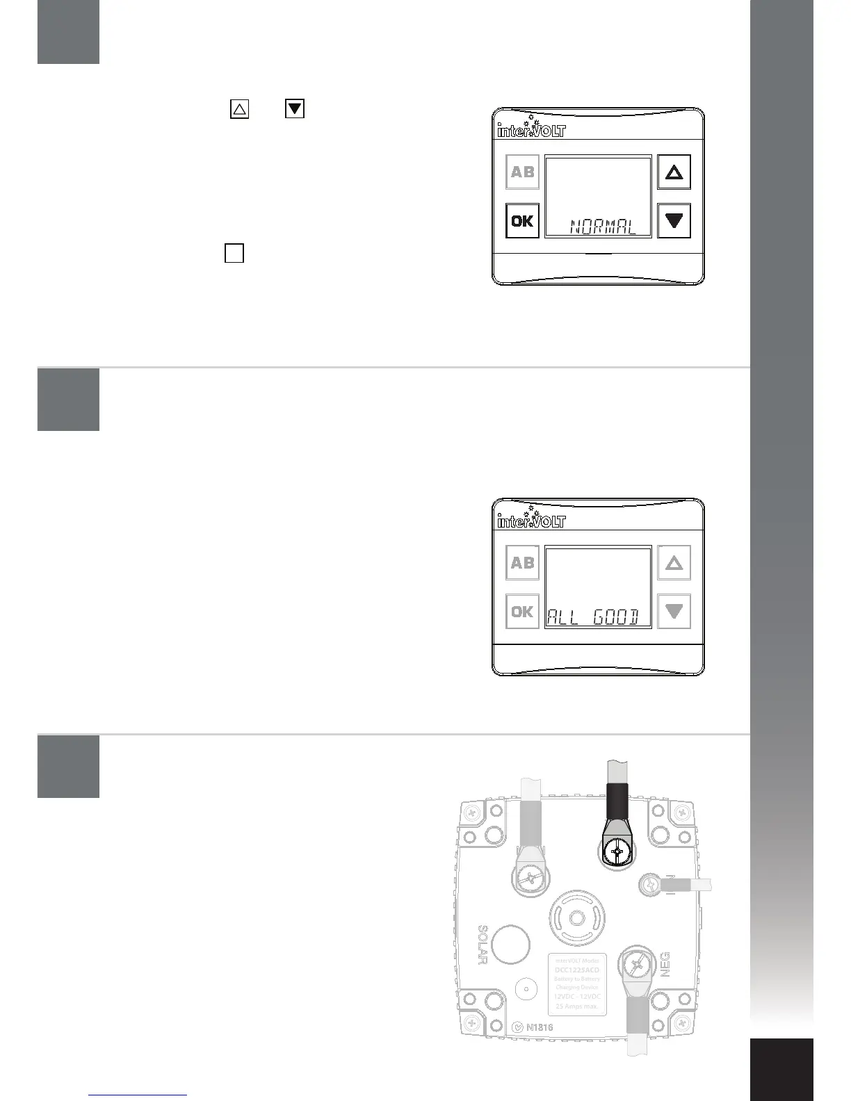
Upon successful completion of the above, the
following conrmation message should appear:
ALL GOOD - this indicates your selections have
been sent to the device and accepted. It does not
conrm the integrity of your wiring installation.
In the event a SYS message error is displayed,
disconnect, then reconnect, the main battery
positive cable and re-commence step 6. If the
error persists re-check the Data Cable connection.
If this does not resolve the problem, please refer
to the troubleshooting information on page 33.
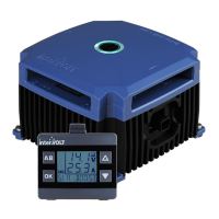
The next step is to conrm the ignition control
setting. Use the and buttons to select one
of the two following options:
I. Select NORMAL for standard (non
CAN/LIN) controlled charging system.
II. Select LOW for ECU controlled
electrical system.
III. Press the button to conrm and
continue to next step.
OK
Connect the auxiliary battery cable
to the Charging Device
Configure the Charging Device: Confirming configuration
Configure the Charging Device: Ignition control setting