28
6. Reinstall the rear wheel to the wheelchair. Refer to Removing/Installing Rear Wheels
paragraph.
7. Repeat STEPS 1
~
6 for opposite wheel, if necessary.
Adjusting the Wheelbase Length
NOTE: For this procedure, refer to FIGURES 5.5 and 5.6
1. Remove the wheel. Refer to Removing/Installing Rear Wheels paragraph.
2. Remove the two mounting screws that secure the top and bottom of the axle plate to
the wheelchair frame.
C A U T I O N
The top of the axle plate must remain on the plastic seat bracket.
Otherwise, scratching and slight frame damage may occur.
3. Align the axle plate with one of four adjustment holes. There are 3 positions possible:
Factory setting for Fixed backrest is Standard position “A”, for Recliner backrest is
Passive position “B” or “C” for some configuration. Refer to detail “A” of FIGURE 5.6 .
W A R N I N G
The two mounting screws need to be two adjustment holes apart to maintain frame
integrity. Respect factory settings related to backrest type (“A” for Fixed, “B” for
Recliner), refer to detail “A” of FIGURE 5.6 .
Medium position “C” of the axle plates directly relate to the stability of the
wheelchair. Only change to one or any combination of the 3 positions may
cause the wheelchair to increase/decrease in stability.
Anti-tippers can be fitted to secure the stability if required. Refer to SECTION 9.
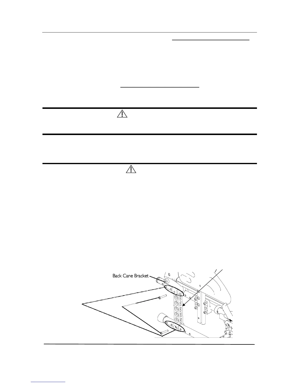
NOTE: When using the last adjustment position, the existing mounting screw needs to be
switched to the front of the back cane bracket.
4. Repeat STEPS 1 to 3 for the other axle plate.
NOTE: Both axle plates should be set at the same position. Head of bottom mounting
screws needs to be on the outside position.
.