28
OPERATION AND SET-UP ON THE CONTROLLER
inVENTer Connect controller platform | Operating instructions
Ending device pairing
The system exits the device pairing state when:
• the maximum number of paired devices is reached (max. 16),
• the time is exceeded,
• or a corresponding key entry is made.
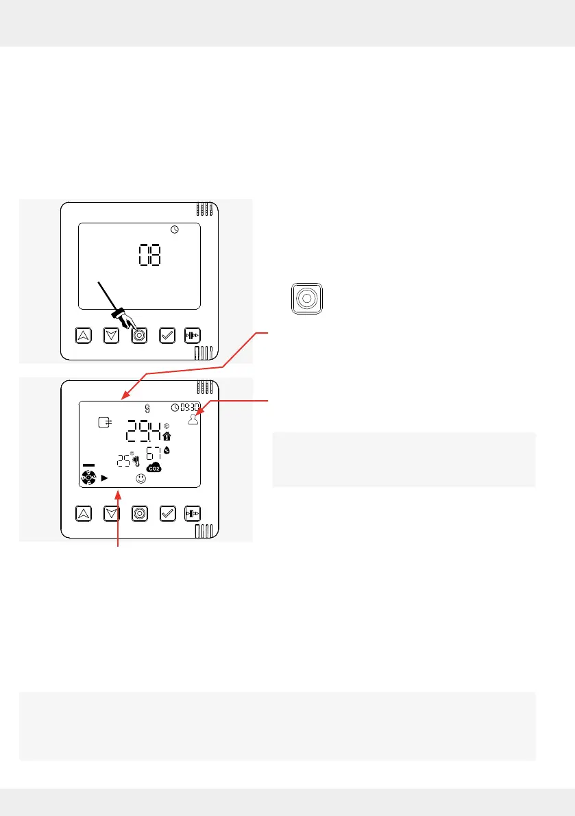
Termination by key entry
Requirements:
• All components relevant to the ventilation system
are paired.
• The display screen shows the number of paired
components.
► Press the mode key to conrm the paired
components.
The display screen shows the information that the
paired system components (inner covers, external
sensors, switching contact) send to the controller.
The system operates in the default prole (factory
settings).
If not already done, the closing ap must be
reattached to the inner cover at this point. See
Page 26; Swivelling the locking arm to the right.
Start screen: System information
After all inner covers (ventilation units) and sensors have been paired with the controller and the
pairing of the components has been conrmed, the ventilation systems starts with the factory
settings, i.e.:
• all ventilation units and sensors are assigned to ventilation zone 1.
• the predened ventilation prole for ventilation zone 1 is set (default prole).
In the factory-set default prole, the system operates at 25 % fan speed and in heat recovery
mode.
It is possible to dene up to four ventilation zones. Dierent ventilation units, sensors and proles
can be assigned to the individual ventilation zones.
Please note: additional ventilation zones can only be set up via the app ( 4: Operation and
set-up with the app).