Page 10
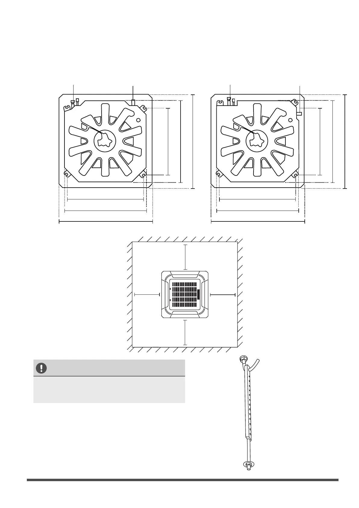
18-48K ceiling hole size 60K ceiling hole size
CAUTION
The unit body should align perfectly with the
hole. Ensure that the unit and the hole are the
same size before moving on.
2. Drill 4 holes 5cm (2”) deep at the ceiling hook
positions in the internal ceiling. Be sure to hold
the drill at a 90° angle to the ceiling.
3. Using a hammer, insert the ceiling hooks into
the pre-drilled holes. Secure the bolt using the
included washers and nuts.
4. Install the four suspension bolts (See Fig. 4.4).
Fig. 4.4
Step 2: Hang indoor unit.
1. Use the included paper template to cut a rectangular hole in the ceiling, leaving at least 1m (39”)
on all sides. The cut hole size should be 4cm(1.6”) larger than the boby size(See Fig. 4.3).
Be sure to mark the areas where ceiling hook holes will be drilled.
Fig. 4.3
Refrigerant piping side
Drain hose side
84cm / 33” (Suspension bolt)
90cm / 35.4” (Body)
102cm / 40.2” (Ceiling opening)
84cm / 33”
(Suspension bolt)
90cm / 35.4” (Body)
102cm / 40.2” (Ceiling opening)
>1m / 39”
>1m / 39”
>1m / 39”
>1m / 39”
Refrigerant piping side
Drain hose side
78cm / 30” (Suspension bolt)
84cm / 33”(Body)
95cm / 37.4”(Ceiling opening)
68cm / 26”
(Suspension bolt)
84cm / 33” (Body)
95cm / 37.4” (Ceiling opening)
Page 11
Installation
5. Mount the indoor unit. You will need two
people to lift and secure it. Insert suspension
bolts into the unit’s hanging holes. Fasten
them using the included washers and nuts
(See Fig. 4.5).
Fig. 4.5
NOTE:
The bottom of the unit should be
10 - 18mm (0.4-0.7”) higher than the ceiling
board. Generally, L (indicated in Fig. 4.6) should
be half the length of the suspension bolt or long
enough to prevent the nuts from coming off.
Fig. 4.6
CAUTION
Ensure that the unit is completely level.
Improper installation can cause the drain pipe to
back up into the unit or water leakage.
Wall
Ceiling board
Main body
10 - 18mm (0.4-0.7”)
L
NOTE:
Ensure that the indoor unit is level. The
unit is equipped with a built-in drain pump and
float switch. If the unit is tilted against the
direction of condensate flows (the drainpipe
side is raised), the float switch may malfunction
and cause water to leak.
Fig. 4.7
NOTE FOR NEW HOME INSTALLATION
When installing the unit in a new home, the
ceiling hooks can be embedded in advance.
Make sure that the hooks do not come loose
due to concrete shrinkage. After installing the
indoor unit, fasten the installation paper
template onto the unit with bolts (M6X12) to
determine in advance the dimension and
position of the opening on the ceiling. Follow
the instructions above for the remainder of the
installation.
Installation template
M6 x 12 Bolts
Main body
Fig. 4.8
 Loading...