Page 24
MODEL
(Btu/h)
≤18K 19K~24K 25K~36K 37K~48K 49K~60K
POWER
(indoor)
PHASE 1 Phase 1 Phase 1 Phase 1 Phase 1 Phase
220-240V 220-240V 220-240V220-240V 220-240V
CIRCUIT BREAKER/
FUSE(A)
15/10 15/10 15/10 15/10 15/10
POWER
(outdoor)
PHASE 1 Phase 1 Phase 1 Phase 1 Phase 1 Phase
208-240V 208-240V 208-240V
208-240V
208-240V
CIRCUIT BREAKER/
FUSE(A)
25/20 25/20 40/30 50/40 50/40
MODEL
(Btu/h)
≤36K 37K~60K ≤36K 37K~60K
POWER
(indoor)
PHASE 1 Phase 1 Phase 1 Phase 1 Phase
208-240V 208-240V 208-240V 208-240V
CIRCUIT BREAKER/FUSE(A) 15/10 15/10 15/10 15/10
POWER
(outdoor)
PHASE 3 Phase 3 Phase 3 Phase 3 Phase
380-420V 380-420V 208-240V 208-240V
CIRCUIT BREAKER/FUSE(A) 25/20 32/25 32/25 45/35
MODEL
(Btu/h)
≤36K 37K~60K ≤36K 37K~60K
POWER
(indoor)
PHASE 1 Phase 1 Phase 1 Phase 1 Phase
220-240V 220-240V 220-240V 220-240V
CIRCUIT BREAKER/FUSE(A) 15/10 15/10 15/10 15/10
POWER
(outdoor)
PHASE 3 Phase 3 Phase 3 Phase 3 Phase
380-420V 380-420V 208-240V 208-240V
CIRCUIT BREAKER/FUSE(A) 25/20 32/25 32/25 40/30
Inverter Type A/C Power Specications
VOLT
VOLT
VOLT
VOLT
VOLT
VOLT
VOLT
VOLT
Independent Power Supply Specications
MODEL
(Btu/h)
≤18K 19K~24K 25K~36K 37K~48K 49K~60K
POWER
(indoor)
PHASE 1 Phase 1 Phase 1 Phase 1 Phase 1 Phase
208-240V 208-240V 208-240V208-240V 208-240V
CIRCUIT BREAKER/
FUSE(A)
15/10 15/10 15/10 15/10 15/10
POWER
(outdoor)
PHASE 1 Phase 1 Phase 1 Phase 1 Phase 1 Phase
208-240V 208-240V 208-240V
208-240V
208-240V
CIRCUIT BREAKER/
FUSE(A)
25/20 32/25 50/40 70/55 70/60
Page 25
Air Evacuation
Safety Precautions
CAUTION
• Use a vacuum pump with a gauge reading
lower than -0.1MPa and an air discharge capacity
above 40L/min.
• The outdoor unit does not need vacuuming.
DO NOT open the outdoor unit’s gas and
liquid stop valves.
• Ensure that the Compound Meter reads
-0.1MPa or below after 2 hours. If after
three hours of operation and the gauge
reading is still above -0.1MPa, check if there
is a gas leak or water inside the pipe. If
there is no leakage, perform another
evacuation for 1 or 2 hours.
• DO NOT use refrigerant gas to evacuate the
system.
Evacuation Instructions
Before using manifold gauge and vacuum pump,
read their operation manuals to familiarize
yourself with how to use them properly.
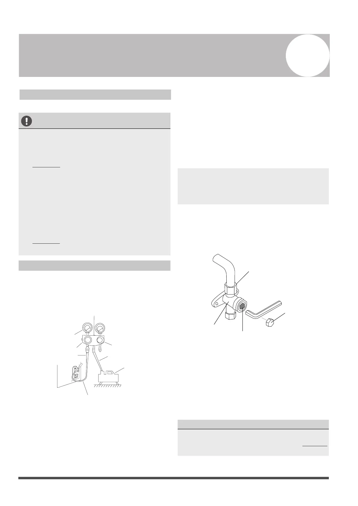
Manifold Gauge
Compound gauge
-76cmHg
Low pressure valve
High pressure valve
Charge hose
Charge hose
Vacuum pump
Pressure gauge
Low pressure valve
Fig. 9.1
1. Connect the charge hose of the manifold
gauge to service port on the outdoor unit’s
low pressure valve.
2. Connect another charge hose from the
manifold gauge to the vacuum pump.
3. Open the Low Pressure side of the manifold
gauge.Keep the High Pressure side closed.
4. Turn on the vacuum pump to evacuate the
system.
5. Run the vacuum for at least 15 minutes, or
until the Compound Meter reads -76cmHG
(-1x10⁵Pa).
6. Close the Low Pressure side of the manifold
gauge, and turn off the vacuum pump.
7. Wait for 5 minutes, then check that there has
been no change in system pressure.
NOTE: If there is no change in system pressure,
unscrew the cap from the packed valve (high
pressure valve). If there is a change in system
pressure, there may be a gas leak.
8. Insert hexagonal wrench into the packed valve
(high pressure valve) and open the valve by
turning the wrench in a 1/4 counterclockwise
turn. Listen for gas to exit the system, then
close the valve after 5 seconds.
Flare nut
Cap
Valve stem
Fig. 9.2
9. Watch the Pressure Gauge for one minute to
make sure that there is no change in pressure.
The Pressure Gauge should read slightly higher
than atmospheric pressure.
10.Remove the charge hose from the service port.
11.Using hexagonal wrench, fully open both the
high pressure and low pressure valves.
OPEN VALVE STEMS GENTLY
When opening valve stems, turn the hexagonal
wrench until it hits against the stopper. DO NOT
try to force the valve to open further.
12.Tighten valve caps by hand, then tighten it
using the proper tool.
9
 Loading...