Goodrive350 IP55 High-ingress Protection Series VFD Basic Operation Instructions
-55-
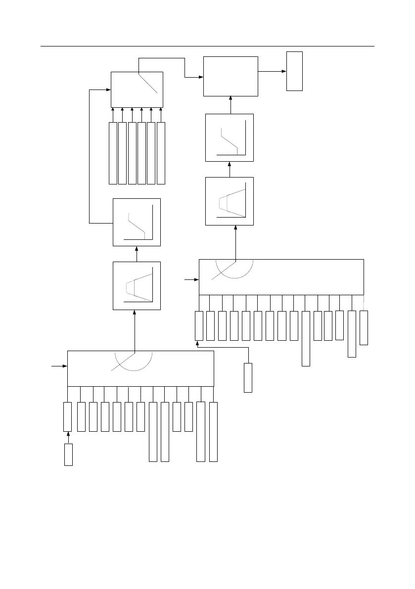
V /F curve
Straight-type V/F curve
Multi-point V/F curve
Customized V/F curve
Torque-down V/F curve
(power of 2.0)
Torque-down V/F curve
(power of 1.7)
Torque-down V/F curve
(power of 1.3)
PWM output
Frequency setup
Voltage setup
P04.29 voltage acceleration time
P04.30 voltage deceleration time
P04.31 output max. voltage
P04.32 output min. voltage
P00.11 acceleration time 1
P00.12 deceleration time 1
P00.04 running frequency
upper limit
P00.05 running frequency
lower limit
P04.00 Motor 1 V/F curve setup
0
1
2
3
4
5
6
7
8
9
10
Keypad
AI1
PROFIBUS/CANopen/DeviceNet
Modbus/Modbus TCP
PID
Multi-step speed
HDIA
AI3
AI2
Ethernet
HDIB
P04.27(volta
ge setup
channel)
P04.28
0
1
2
3
4
5
6
7
8
9
10
11
Keypad
AI1
PROFIBUS/CANopen/
DeviceNet
Modbus/Modbus
TCP
PID
Multi-step speed
Simple PLC
HDIA
AI3
AI2
Ethernet
HDIB
P00.06
(A frequency
command
selection)
Keypad setting
frequency
P00.10
0
1
2
3
4
5
EtherCAT/PROFINET/EtherNet IP
Programmable card
Pulse train AB
EtherCAT/PROFINET/
EtherNet IP
Programmable
card
11
12
12
13
14
When selecting customized V/F curve function, users can set the reference channels and
acceleration/deceleration time of voltage and frequency respectively, which will form a
real-time V/F curve through combination.
Note: This kind of V/F curve separation can be applied in various frequency-conversion power
sources, however, users should be cautious of parameter setup as improper setup may
damage the machine.
 Loading...