EasyManua.ls Logo

INVT Goodrive200A Series User Manual

INVT Goodrive200A Series
182 pages
To Next Page IconTo Next Page
To Previous Page IconTo Previous Page
Page #51 background imageLoading...
Page #51 background image
GD200A series VFD Function parameters
-44-
Function
code
Name
Description
Default
value
Modify
speed
time of P01.17, the VFD will stop; otherwise the
VFD will stop after the set time of P01.17.
T
Stop speed
A
Ramp reference
frequency
Output frequency
Frequency
P01.24 P01.17
B
C
Running A
Running B
Running C
Setting range: 0.00100.00s (only valid when
P01.16=1)
P01.18
Operation
protection
during
powering on
When the running command channel is the
terminal control, the system will detect the state of
the running terminal during powering on.
0: The terminal running command is invalid when
powering on. Even the running command is
detected to be valid during powering on, the VFD
won’t run and the system keeps in the protection
state until the running command is canceled and
enabled again.
1: The terminal running command is valid when
powering on. If the running command is detected
to be valid during powering on, the system will
start the VFD automatically after the initialization.
Note: This function should be selected with
cautions, or serious result may follow.
0
P01.19
Action selection
when running
frequency is
lower than
lower limit of
frequency
(valid when low
limit of
frequency is
larger than 0)
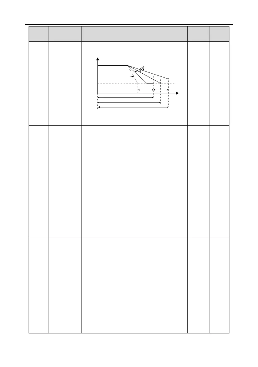
This function code determines the running state of
the VFD when the set frequency is lower than the
lower-limit one.
0: Run at the lower limit frequency
1: Stop
2: Hibernation
The VFD will coast to stop when the set frequency
is lower than the lower-limit one. If the set
frequency is above the lower limit one again and it
lasts for the time set by P01.20, the VFD will come
back to the running state automatically.
3: Sleep and standby 2
Select sleep and standby 2: When the running
0

Table of Contents

Question and Answer IconNeed help?

Do you have a question about the INVT Goodrive200A Series and is the answer not in the manual?

INVT Goodrive200A Series Specifications

General IconGeneral
BrandINVT
ModelGoodrive200A Series
CategoryDC Drives
LanguageEnglish

Summary

Preface

Safety Definition

Defines terms like Danger, Warning, and Note for safety communication.

Warning Symbols

Explains symbols used for warnings: Danger, Warning, Do not touch, Hot.

Safety Precautions

Safety Definition

Defines terms like Danger, Warning, and Note for safety communication.

Warning Symbols

Explains symbols used for warnings: Danger, Warning, Do not touch, Hot.

Safety Guidelines

Delivery and Installation Safety

Guidelines for safe delivery, handling, and installation of the VFD.

Commissioning and Running Safety

Maintenance and Component Replacement Safety

Scrap Treatment and Disposal

Quick Start Guide

Unpacking and Initial Inspection

Steps to check the VFD and its accessories after receiving the product.

Application Confirmation

Checks to perform on the load and supply voltage before VFD use.

Installation Environment Requirements

Specifies conditions for ambient temperature, humidity, altitude.

Installation Confirmation

Basic Commissioning Procedures

Product Overview

Basic Principles of VFD Operation

Explains the VFD's rectifier, DC bus, and converter functions.

Product Specifications

Nameplate Information

Type Designation Key

Rated Specifications Summary

VFD Structure Diagram

Installation Guidelines

Mechanical Installation

Covers VFD mounting, orientation, and environment.

Standard Wiring Practices

Details main circuit, control circuit, and I/O wiring.

Layout Protection Measures

Covers protection against short circuits, overload, and interference.

Keypad Operation Procedure

Keypad Overview and Components

Identifies VFD keypad models and their components.

Keypad Display and Basic Operation

Explains VFD display states and basic keypad interactions.

Modifying Function Codes

Setting the VFD Password

Watching VFD State via Function Codes

Function Parameters

General Series Function Parameters

Overview of parameter groups (P00-P29) and their structure.

Protective Parameters

Basic Operation Instruction

First Powering On Procedure

Steps for initial VFD power-up and initialization.

Vector Control Explained

Details the principles and application of vector control for motors.

Torque Control Explained

Explains torque control mode and its relation to speed control.

Motor Parameter Setup Guide

Instructions for setting motor parameters and performing autotune.

Start and Stop Control

Describes VFD start/stop methods and logic diagrams.

Frequency Setting Methods

Explains various ways to set VFD frequency reference.

Simple PLC Functionality

Multi-step Speed Running

PID Control Explained

PID Control Overview

Introduction to PID control for process regulation.

PID Parameter Setting Steps

Guide to setting PID parameters (P, Ti, Td) for optimal control.

Fault Tracking and Troubleshooting

Alarm and Fault Indications

How VFD alarms and faults are indicated via LEDs and display.

Fault Instruction and Solution Guide

Lists fault codes, types, possible causes, and corrective actions.

Common Fault Analysis

Diagnostic flowcharts for common VFD faults.

VFD System Interference Troubleshooting

Methods to identify and mitigate VFD system interference.

Maintenance and Hardware Diagnostics

Procedures for routine VFD inspection and diagnostics.

Cooling Fan Maintenance and Replacement

Capacitor Reforming Procedure

Communication Protocol

MODBUS Protocol Overview

Introduction to MODBUS protocol and its application in VFDs.

RS485 and RTU Mode Application

Details on RS485 interface and RTU communication mode.

Communication Command Examples

Examples of reading and writing commands via RTU and ASCII.

Data Address Definition in MODBUS

Mapping of VFD parameters to MODBUS addresses.

Fault Message Responses in Communication

Explains VFD fault messages returned during communication.

Appendix A: Technical Data

VFD Ratings and Capacity Specifications

Details VFD power, current, voltage, and frequency ratings.

Derating Factors for VFD Operation

Information on derating due to temperature, altitude, and carrier frequency.

EMC Compatibility and Applicable Standards

Details EMC requirements and relevant industry standards.

Appendix B: Dimension Drawings

Keypad Structure and Installation Details

Shows keypad dimensions and mounting options.

VFD Wall Mounting Dimensions

Provides dimensions and mounting hole details for wall installation.

VFD Flange Mounting Dimensions

Details dimensions and mounting hole specifications for flange installation.

VFD Floor Mounting Dimensions

Provides dimensions and mounting details for floor installation.

Appendix C: Peripheral Options and Parts

Peripheral Wiring Overview

Illustrates typical peripheral connections for the VFD.

Power Cables and Control Cables

Details recommended cable types, sizes, and installation.

Breakers and Protection Devices

Guidance on selecting protective devices like breakers and contactors.

Reactors and Filters Selection

Information on selecting appropriate reactors and filters for the VFD.

Braking System Component Selection

Guidance on selecting braking resistors and units.

Other Optional Parts and Accessories

Lists optional parts like side covers, keypads, and installation brackets.

Appendix D: Further Information

Product and Service Inquiries

Contact information for product and service inquiries.

Manual Feedback and Online Resources

Information on providing feedback and accessing online documentation.

Related product manuals