Starting IRMA MATRIX on the PC via Ethernet
released
6 Connecting the sensor
The sensor and computer are connected via the Ethernet. The connection is made using an
Ethernet switch.
6.1 PC connection with a standard connector of the type
sCON-S-CAN-ETH-23-Kq-x-y
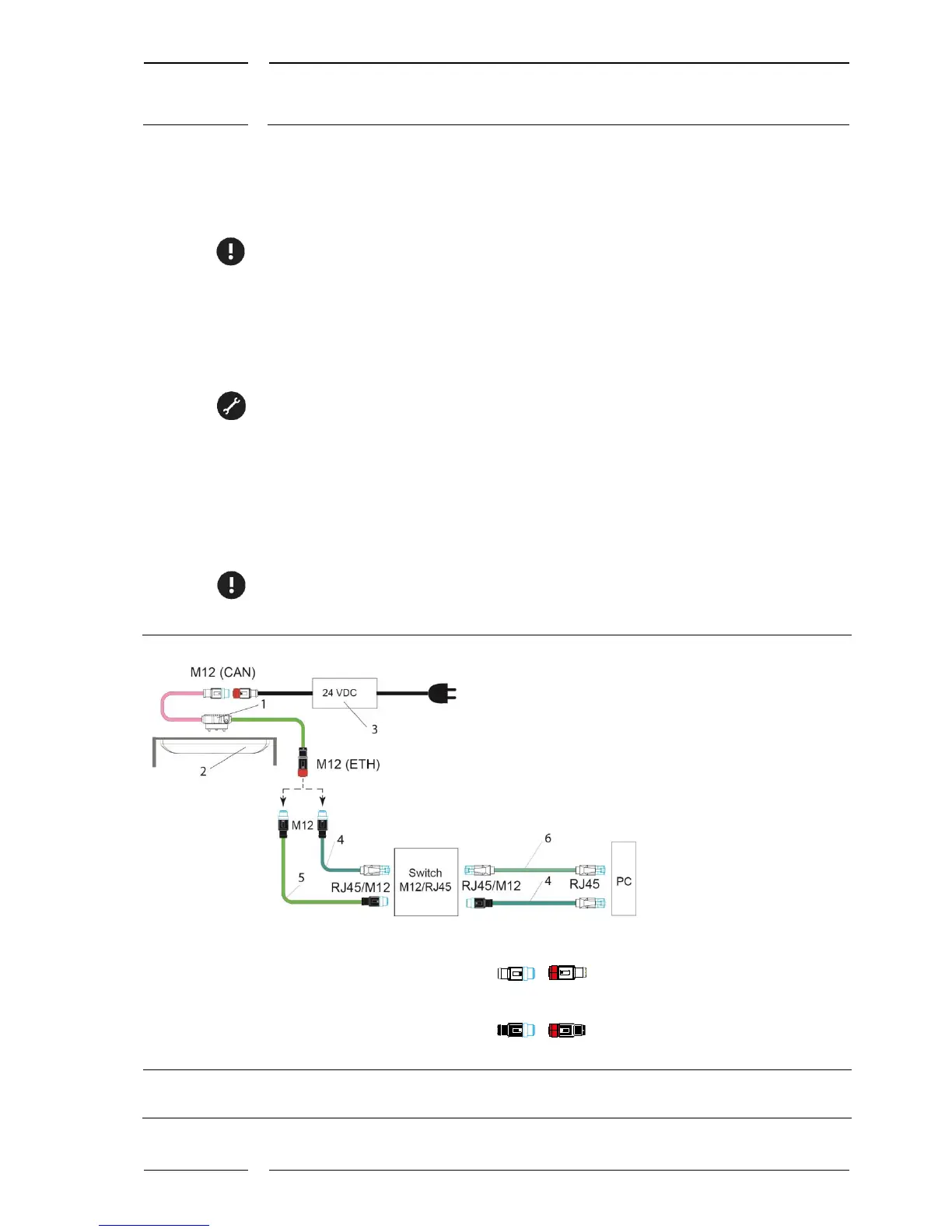
1. Connect the IRMA MATRIX sensor with the connector. See Figure 4.
2. Connect the Ethernet interface of the sensor (M12 female connector, 4 poles) to the
M12 connector (male, 4 poles), using an adapter cable (see Figure 4 with item (4) or
(5)).
3. Connect the adapter cable to the switch.
4. Connect the switch with the PC (see Figure 4 with item (4) or (6)).
5. Connect the CAN interface of the sensor (M12 male connector type CAN to the M12
female connector (type CAN) of the Power block (item 3).
6. The final step is to connect the power block to power supply!
1 IRMA MATRIX sensor (flush mount or surface mount version)
2 Standard connector with interfaces CAN and Ethernet
of type sCON-S-CAN-ETH-23-Kq-x-y
3 Power block 24 V-M12
4 Adapter cable for connection to the RJ45-switch
KQ-M12CAT5-RJ45-01-xm
5 M12 Ethernet system cable for connection to the M12-switch
K-M12CAT5-XX-xm
6 Commercial patch cable with 2x RJ45 connectors
M12 male connectors are marked by blue contours
M12 female connectors are filled in in red
...
M12 connector (m, f) of type CAN are 5 pole and A coded.
M12 connector (m, f) of type ETH are 4 pole and D coded
Figure 4: PC connection with sCON-S-CAN-ETH-23-Kq-x-y standard