Starting IRMA MATRIX on the PC via Ethernet
released
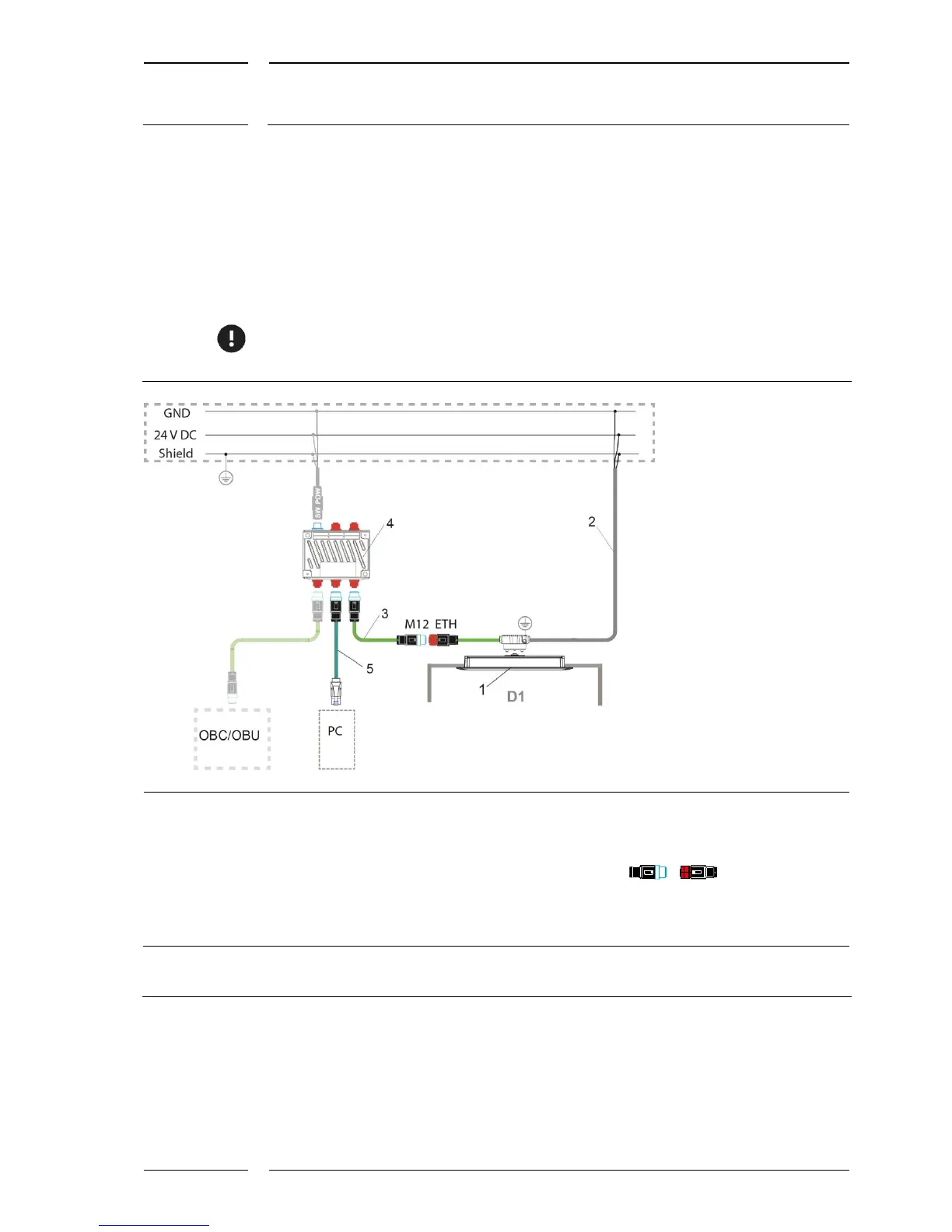
6.2 PC connection with a standard connector of the
sCON-S-ETH-22-Kq-x-y type
This sCON is installed in vehicles fitted with a switch. On installation the sensor power
supply is connected as specified in the installation instructions. Connect the PC to the
switch using suitable cables, see Figure 5, item 5.
For service work, you first need to ascertain the connector type of the switch. An adapter
can be necessary. The most common types are e.g.: SUB-D9, RJ45, M12 (D coded).
1 IRMA MATRIX sensor DIST500-A/DIST500-F
(surface mount or flush mount version)
2 Standard connector with Ethernet interface:
sCON-S-ETH-22-Kq-x-y
3 M12 system cable type ETH, K-M12CAT5-XX-x
4 Switch e.g. Switch-M12-5Port-eCon
5 M12-RJ45 adapter cable type ETH
KQ-M12CAT5-RJ45-01-xm
OBC/OBU:
On-Board Computer/On-Board Unit
D1 Door 1
M12 male connectors are marked by blue
contours
M12 female connectors are filled in in red
M12 connector (m, f) of type ETH
are 4 pole and D coded.
Figure 5: PC connection with sCON-S-ETH-22-Kq-x-y