I A P 2 0 2 3 . 0 0 1 - A F M / I R I S T E X A N I I P A G E | 34
FOR SIMULATION USE ONLY – NOT A TRAINING AID
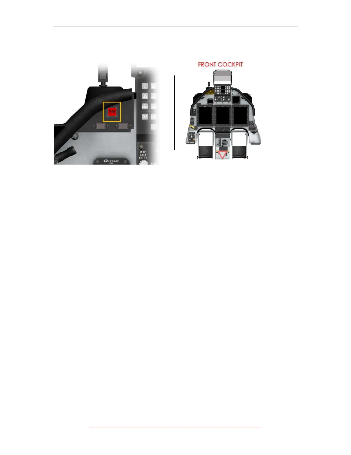
FIRE WARNING SYSTEM
Figure 1-11 Fire Warning Light Location
The aircraft is equipped with a fire warning system that includes dual sensor tubes
and responder assemblies. The sensors, mounted around the exterior surface of
the engine, signal the respective responder assembly when a high temperature is
detected.
The sensor tubes contain helium gas and a hydrogen charged core material. The
helium gas responds to the sensor's overall threshold temperature for temperature
sensing.
The hydrogen charged core responds to highly localized heat caused by flames
and/or escaping hot bleed air gases resulting in the release of hydrogen gas from
the core, which increases the helium gas pressure.
Sensor heating expands the helium gas, which in turn pressurizes a diaphragm
inside the responder. If the diaphragm pressure reaches or exceeds the preset fire
detection point, an electrical circuit triggers the red FIRE annunciator light and
sounds the aural tone.
A fire warning system test switch, labelled FIRE, is provided on the front cockpit left
console test panel to verify the electrical continuity of the two fire warning systems.
Momentarily selecting the placarded 1 or 2 position will check system integrity and
lamp operation for the respective system.
When the test switch is set to 1, the upper half of the annunciator will illuminate;
when set to 2, the lower half of the annunciator will illuminate.
Flattening, twisting, kinking or denting of the fire warning loop does not affect test
or flight operation.